
MELC-102 · Lesson 7 of 12 · 24 min
Voltage drop calculations
▶ Video coming soon A video version of this lesson is on the way.
Ampacity keeps conductors from overheating. Voltage drop keeps equipment working properly at the end of the run. Every conductor has resistance, so current flowing through it loses some voltage along the way, and on a long run the voltage at the load can fall far enough to make motors run hot, lights dim and electronics misbehave. The CE Code limits voltage drop in Rule 8-102, and voltage drop questions are a staple of every licensing exam because they combine Ohm's law, conductor data and judgement about which limit applies.
This lesson covers the voltage drop limits, the formulas for single-phase and three-phase circuits, where conductor resistance data comes from, the shortcut tables in Appendix D, and how to size a conductor for a long run. The Hartley Farms bin yard, where Parkland Valley ran a feeder over 100 m to a new set of grain bins and their aeration fans, is the running example.
The limits in Rule 8-102
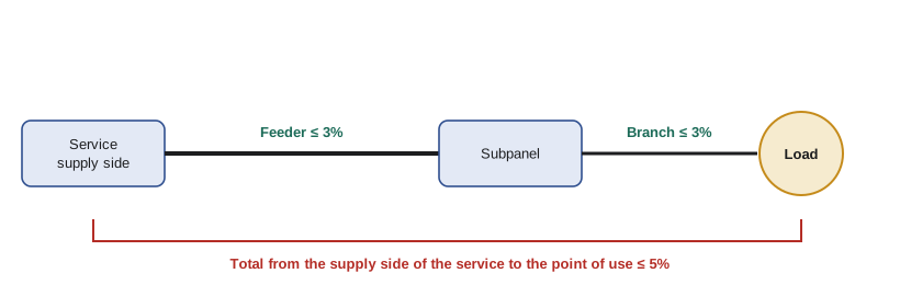
Rule 8-102 sets two limits, expressed as a share of the supply voltage. The voltage drop in a feeder or a branch circuit is not to exceed 3%, and the total voltage drop from the supply side of the consumer's service to the point of use is not to exceed 5%. The rule bases the calculation on the connected load of the circuit or, where it is known, on the demand load, and the rule has more detail about which current to use; read it in your Code. The two limits work together: a design might allow 2% in the feeder and 3% in the branch circuit, staying within 3% for each and 5% overall.
| Part of the system | Limit (Rule 8-102, summarised) | At 240 V | At 600 V |
|---|---|---|---|
| Feeder | 3% | 7.2 V | 18 V |
| Branch circuit | 3% | 7.2 V | 18 V |
| Total from service to point of use | 5% | 12 V | 30 V |
The basic formula
Voltage drop in a conductor is current times resistance. In a single-phase two-wire or 120/240 V circuit, the current flows out on one conductor and back on the other, so the length of conductor carrying the current is twice the one-way run length. In a balanced three-phase circuit, the geometry of the phases makes the effective multiplier the square root of three instead of two. These two formulas, with resistance per unit length, answer almost every exam voltage drop question.
Here L is the one-way length in metres, I is the current in amperes and R is the conductor resistance in ohms per kilometre, which is why the formula divides by 1000. For larger conductors and AC circuits, reactance becomes significant and an impedance value replaces resistance, but for the sizes most exam questions use, resistance alone is close enough and is what the questions expect unless they give an impedance.
Conductor resistance depends on material, size and temperature. Resistance values are available from conductor manufacturers and engineering references, usually at 20 °C and at operating temperatures like 75 °C. The values below are approximate DC resistances at 75 °C, given here as general engineering data for teaching; check them against your references and use the conductor temperature the question specifies.
| Copper size | Approx. resistance at 75 °C (Ω/km) | Aluminum size | Approx. resistance at 75 °C (Ω/km) |
|---|---|---|---|
| 14 AWG | 10.2 | 12 AWG | 10.6 |
| 12 AWG | 6.4 | 10 AWG | 6.6 |
| 10 AWG | 4.0 | 8 AWG | 4.2 |
| 8 AWG | 2.5 | 6 AWG | 2.6 |
| 6 AWG | 1.6 | 4 AWG | 1.7 |
| 4 AWG | 1.0 | 2 AWG | 1.0 |
| 2 AWG | 0.63 | 1/0 AWG | 0.66 |
| 1/0 AWG | 0.40 | 3/0 AWG | 0.41 |
Worked problem
A branch circuit in the machine shed
A 240 V single-phase heater draws 16 A at the end of a 45 m run of 12 AWG copper. Using about 6.4 Ω/km, what is the voltage drop, and is it within 3%?
Show solution
- Vd = 2 × 45 × 16 × 6.4 / 1000 = 9.2 V.
- 3% of 240 V is 7.2 V. 9.2 V exceeds it.
- Try 10 AWG at about 4.0 Ω/km: 2 × 45 × 16 × 4.0 / 1000 = 5.8 V, which is 2.4% and within the limit.
Answer: 9.2 V (3.8%) with 12 AWG, too much; 10 AWG gives 5.8 V (2.4%).
Sizing a conductor for a long run
Exams usually turn the formula around: given the load, the length and the allowed drop, find the smallest conductor that works. Rearranging gives the maximum resistance per kilometre the conductor may have. Then you choose the first size whose resistance is at or below that value, and check that its ampacity is also enough.
Worked problem
The bin yard feeder
The Hartley Farms bin yard needs a 120/240 V single-phase feeder carrying 80 A over a one-way distance of 110 m. The farm's service already drops 1% before the feeder starts, so Priya allows 2% for the feeder to keep the total within 5% with room for the branch circuits. Find the maximum resistance and choose an aluminum conductor.
Show solution
- Allowed drop: 2% of 240 V = 4.8 V.
- R max = 4.8 × 1000 / (2 × 110 × 80) = 4800 / 17 600 = 0.273 Ω/km.
- From the illustrative table, 3/0 aluminum at about 0.41 Ω/km is too high. A larger size near 0.27 Ω/km is needed, about 250 kcmil aluminum, or 3/0 copper at about 0.25 Ω/km.
- Ampacity for 80 A is easily met by either; voltage drop governs this run.
Answer: About 0.27 Ω/km maximum; roughly 250 kcmil aluminum or 3/0 copper.
This is the typical result for long runs: the conductor needed for voltage drop is several sizes larger than the one needed for ampacity. On farms, in parking lots and on large sites, voltage drop usually governs. In compact buildings, ampacity usually does.
Three-phase voltage drop
For a balanced three-phase load, use the square root of three instead of 2 in the formula, with the line current and the one-way length. The result is the line-to-line voltage drop, which you compare with the same share of the line-to-line voltage. Three-phase circuits have less voltage drop than single-phase circuits carrying the same power, for two reasons: the higher voltage means less current, and the multiplier is 1.732 instead of 2.
Worked problem
Aeration fans at 600 V
The aeration fans are fed at 600 V three-phase, 45 A per line, over 110 m of 4 AWG copper (about 1.0 Ω/km). What is the voltage drop?
Show solution
- Vd = 1.732 × 110 × 45 × 1.0 / 1000 = 8.6 V.
- As a share of 600 V: 8.6 / 600 = 1.4%.
Answer: About 8.6 V, 1.4%: comfortably within 3%.
The Appendix D tables
Appendix D of the Code includes tables that let you check voltage drop without the formula. One commonly used table gives, for each conductor size and a range of currents, the distance to the load that produces a 1% voltage drop on a 120 V two-wire circuit, with multipliers for other voltages and multipliers. The method is to look up the 1% distance, multiply by the share allowed and by the voltage factor, and compare the result with the actual run length. Appendix D is informative, not mandatory, but it is accepted as a calculation method and it is fast on an exam if you know how to use it.
Because the table values are the Code's content, they are not reproduced here. The logic is easy to see from the formula: the distance for 1% drop at 120 V is the length at which 2 × L × I × R / 1000 equals 1.2 V. A 240 V circuit allows twice the volts for the same share, so the distance doubles; a 3% allowance triples it. Practise with your own Appendix D until the multipliers are second nature, then check one result each time with the formula, which is Denise's insurance against misreading a column.
Worked problem
Checking with the 1% distance idea
For a 120 V circuit carrying 15 A on 12 AWG copper (about 6.4 Ω/km), what length gives a 1% drop? How far could the same circuit run at 240 V with a 3% allowance?
Show solution
- 1% of 120 V = 1.2 V. L = 1.2 × 1000 / (2 × 15 × 6.4) = 1200 / 192 = 6.25 m.
- At 240 V the volts allowed double, and at 3% they triple: 6.25 × 2 × 3 = 37.5 m.
Answer: About 6.3 m for 1% at 120 V; about 37.5 m at 240 V with 3%.
That first result surprises people: a fully loaded 120 V, 15 A circuit on 12 AWG reaches a 1% drop in only about 6 m, and the 3% limit at about 19 m. Real branch circuits are rarely loaded to their full rating at the far end, which is why the rule lets you use the actual load, but the arithmetic shows why long 120 V runs at high load need larger conductors.
Voltage drop and motors
Motors are sensitive to voltage. A motor running at reduced voltage draws more current to deliver the same mechanical load, which heats the windings, and at starting, when current is several times full load, the voltage drop is several times larger. A long feeder that meets the 3% limit at running current may still let the voltage sag badly on starting, making contactors chatter and lights dip. The Code's limit is for running conditions; good design checks starting too, and exam questions occasionally ask about it qualitatively.
120 V loads on a 120/240 V feeder
The single-phase formula assumes the current goes out on one conductor and comes back on the other. On a 120/240 V feeder with balanced 120 V loads, the neutral carries almost nothing, and the drop that matters is along the two line conductors; it is easiest to treat the load as a 240 V load and use the 240 V formula. When the 120 V loads are badly unbalanced, the neutral carries current too, and the voltage drop on the heavily loaded side includes a drop along the neutral. The worst case is a single 120 V load on one line with nothing on the other: then the current flows out on one line and back on the neutral, and the drop is 2 × L × I × R against a supply of only 120 V, so the share of the supply is twice what the same current would give on a 240 V load.
This is why Priya balances the bin yard subpanel carefully. With the aeration fan controls, receptacles and yard lights split evenly between the two lines, the feeder behaves like a 240 V load and the 2% design works. If an electrician later added several 120 V loads to one side, the voltage on that side would sag noticeably at the far end, even though the feeder still met the rule when it was installed.
Measuring the result
After the bin yard feeder was energised, Priya measured the voltage at the subpanel with the fans and dryer burners running: 236 V, against 240 V at the farm's main panel. That is a 4 V drop, about 1.7%, slightly better than the 2% design because the measured load was below the calculated 80 A. The meter confirms the arithmetic and gives the farm a baseline: if the reading falls in later years, something has changed, such as added load, a loose connection or a deteriorating splice.
Exams cannot hand you a meter, but they can give measured voltages and ask you to work out the drop, the share of the supply voltage or the current. They are the same formulas in a different order.
A calculator for long runs
import math

R75 = {  # approximate ohms per km at 75 C (teaching values, not Code tables)
    'Cu 12': 6.4, 'Cu 10': 4.0, 'Cu 8': 2.5, 'Cu 6': 1.6, 'Cu 4': 1.0,
    'Cu 2': 0.63, 'Cu 1/0': 0.40, 'Cu 3/0': 0.25,
}

def vdrop(length_m, amps, ohm_per_km, phases=1):
    k = 2 if phases == 1 else math.sqrt(3)
    return k * length_m * amps * ohm_per_km / 1000

def smallest(length_m, amps, volts, pct, phases=1):
    for size, r in R75.items():
        if vdrop(length_m, amps, r, phases) <= volts * pct / 100:
            return size, vdrop(length_m, amps, r, phases)
    return None, None

print(smallest(45, 16, 240, 3))            # machine shed heater
print(smallest(110, 80, 240, 2))           # bin yard feeder
print(round(vdrop(110, 45, 1.0, 3), 1)) # aeration fans, 600 V('Cu 10', 5.76)
('Cu 3/0', 4.4)
8.6Try the bin yard with a 3% allowance instead of 2% and see how much smaller the conductor gets. That trade-off, between spending voltage drop in the feeder or in the branch circuits, is a real design decision.
Common mistakes
MistakeUsing the one-way length without the factor of 2 for single-phase.
InsteadSingle-phase drop uses 2 × L; three-phase uses 1.732 × L.
MistakeComparing a three-phase drop with the line-to-neutral voltage.
InsteadCompare the line-to-line drop with the line-to-line voltage.
MistakeChecking only the feeder and forgetting the 5% total.
InsteadThe feeder and branch circuit each stay within 3%, and the total within 5%.
MistakeSizing for ampacity and stopping.
InsteadOn long runs, check voltage drop; it often needs a larger conductor.
MistakeForgetting to convert ohms per kilometre.
InsteadDivide by 1000 when the length is in metres and R is in ohms per kilometre.
Summary and key terms
- Rule 8-102 limits voltage drop to 3% in a feeder or branch circuit and 5% total from the service to the point of use.
- Single-phase: Vd = 2 × L × I × R / 1000; three-phase: Vd = 1.732 × L × I × R / 1000.
- Rearrange for the maximum resistance per kilometre to size a conductor for a long run.
- Appendix D's tables give distances for a 1% drop, with multipliers for voltage and the allowed share.
- On long runs, voltage drop usually governs conductor size; on short runs, ampacity does.
- Voltage drop
- The voltage lost along a conductor because of its resistance and the current through it.
- One-way length
- The distance from the source to the load, measured along the route of the conductors.
- Point of use
- The place where the load is connected.
- Impedance
- The total opposition to AC current, including resistance and reactance.
- Feeder
- Conductors between the service equipment and a branch circuit distribution point.
Practice problems
Work each problem on paper first, then reveal the answer to check.
A 240 V load draws 30 A over 60 m of copper at 1.6 Ω/km. Find the drop.
Show answer
2 × 60 × 30 × 1.6 / 1000 = 5.76 V, 2.4%.
What is 3% of 120 V?
Show answer
3.6 V.
Maximum resistance for 50 A over 80 m single-phase with 6 V allowed?
Show answer
6000 / (2 × 80 × 50) = 0.75 Ω/km.
A three-phase 600 V circuit drops 12 V. Is it within 3%?
Show answer
Yes: 12 / 600 = 2%.
Lesson quiz · 5 questions
Score 60% or more to complete this lesson.
Create a free account to save your progress, take quizzes and earn a certificate.