
MELC-102 · Lesson 6 of 12 · 26 min
Ampacity tables and correction factors
▶ Video coming soon A video version of this lesson is on the way.
A demand calculation tells you how much current a service or feeder must carry. The next question is which conductor can carry it, and that is where the ampacity tables in Section 4 of the CE Code come in. Ampacity is the current a conductor can carry continuously under specified conditions without exceeding its insulation temperature rating. The tables give base ampacities for standard conditions; correction factors adjust them for real conditions such as hot locations or many conductors bundled together; and termination rules limit how much of the conductor's rating you can actually use at the equipment it connects to. Getting all three right is the core skill of conductor sizing.
This lesson covers the structure of the ampacity tables, how to choose the right table and column, temperature and bundling corrections, when neutrals count as current-carrying conductors, termination temperature limits and the continuous-load rules that cap how heavily a conductor may be loaded. The Code's tables are not reproduced here. Where a worked example needs a table value, it uses an illustrative value that is labelled as such, and you should look up the real one in your 2024 Code every time.
How the ampacity tables are organised
Section 4's main ampacity tables are arranged by conductor material and by installation. There are tables for copper and for aluminum, and for each material there is one table for single conductors in free air and another for not more than three conductors in a raceway or cable, or directly buried. Rule 4-004 tells you which table applies to which installation. Within each table, the columns are headed by the temperature rating of the insulation, typically 60 °C, 75 °C and 90 °C, and the rows are conductor sizes from small AWG sizes up to large kcmil sizes.
| Installation | Copper table | Aluminum table |
|---|---|---|
| Single conductors in free air | Table 1 | Table 3 |
| Not more than 3 conductors in raceway or cable, or direct buried | Table 2 | Table 4 |
The free-air tables give higher ampacities because a conductor in open air sheds heat more easily than one enclosed with others in a conduit. The raceway tables assume up to three current-carrying conductors sharing the enclosure. Using the free-air table for conductors in a conduit is one of the classic exam traps, and so is forgetting that a cable with four current-carrying conductors is outside the assumption of the raceway table.
Choosing the column
The temperature column you start from depends on the insulation of the conductor. RW90, T90 Nylon and TECK90 conductors are rated 90 °C in dry locations, and many cables are rated 75 °C or 90 °C depending on the location. But the column you can finally use is also limited by the terminations, as the section on termination limits below explains. A good habit is to note both temperatures at the start: the insulation rating and the lowest rating of any termination the conductor lands on.
Ambient temperature correction
The base ampacities assume an ambient temperature of 30 °C. In hotter places, such as a boiler room, a hot attic, a rooftop conduit in the sun or a grain dryer building at Hartley Farms, the conductor starts closer to its insulation limit and can carry less current. The Code provides correction factors for ambient temperatures above 30 °C, by insulation temperature rating, and you multiply the table ampacity by the factor. Higher-rated insulation loses less of its ampacity in a hot ambient, which is one reason 90 °C conductors are used in hot locations even where terminations limit the final ampacity.
Worked problem
Conductors in the grain dryer building (illustrative values)
A circuit in the Hartley Farms grain dryer building runs in conduit where the ambient reaches 45 °C. Suppose the table ampacity of the chosen copper conductor in the 90 °C column is 75 A and the ambient correction factor for 90 °C insulation at that temperature is 0.87. What is the corrected ampacity?
Show solution
- Corrected ampacity = 75 × 0.87 = 65.3 A (illustrative values).
- If the circuit needs 70 A, this conductor is too small, and the next size up must be checked the same way.
Answer: About 65 A with these illustrative values.
More than three current-carrying conductors
When more than three current-carrying conductors share a raceway or cable, they heat each other, and their ampacity must be reduced. The Code gives correction factors by the number of conductors, stepping down as the number grows. You apply this factor in addition to any ambient correction, multiplying both into the table value.
The key question is what counts as a current-carrying conductor. Equipment bonding conductors never count. A neutral that carries only the unbalanced current of a single-phase three-wire circuit or a balanced three-phase four-wire circuit usually does not count, because its current is the difference between the line currents. But a neutral in a three-phase four-wire system supplying mostly non-linear loads, such as electronic equipment and LED drivers, carries harmonic currents that add up, and it must be counted. The Code has specific rules on this in Section 4; read them in your own Code, because exam questions are built around exactly that distinction.
Worked problem
Eight conductors in one conduit (illustrative values)
At the dental clinic, a conduit carries the line conductors of three 120 V branch circuits and a 3-phase 208 V feeder with neutral supplying LED lighting drivers, plus a bonding conductor. How many current-carrying conductors are there, and what factor applies if the table factor for that number is, say, 0.70?
Show solution
- Branch circuits: three line conductors and their neutrals. A 120 V two-wire circuit's neutral carries the full load current, so each counts: 6 conductors.
- Feeder: 3 line conductors, and the neutral counts because the load is mostly non-linear: 4 conductors.
- Bonding conductor: does not count.
- Total current-carrying conductors: 10. With an illustrative factor of 0.70, each conductor's ampacity is 70% of its table value.
Answer: 10 current-carrying conductors; apply the factor your table gives for that number.
That example shows why the neutral question matters. Treating the feeder neutral as non-current-carrying would give 9 conductors, which in this case falls in the same band, but in other examples the count crosses a step and the answer changes. Examiners pick their numbers to sit right on those steps.
Termination temperature limits
A conductor's ampacity is only as good as the equipment it connects to. Breakers, switches, panelboards and lugs are tested with conductors at a certain temperature, and Rule 4-006 limits the ampacity you can use to the column that matches the termination temperature rating. In general, where equipment is not marked otherwise, smaller circuits are limited to the 60 °C column and larger ones to the 75 °C column; equipment marked for 90 °C terminations is uncommon. The effect is that a 90 °C conductor's higher ampacity is useful mainly as a starting point for corrections, while the final ampacity at the terminals is limited to the 75 °C or 60 °C value.
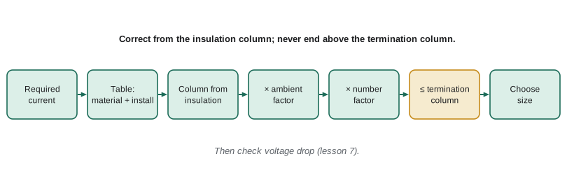
The study group puts it this way: correct from the column your insulation allows, but never end above the column your terminations allow. If you start from the 90 °C value, apply the ambient and bundling factors, and the result is still above the 75 °C table value, the 75 °C table value is your limit. If the corrected value is below it, the corrected value is your limit.
Worked problem
Feeder to the dryer motor control centre (illustrative values)
A copper feeder in conduit needs 110 A. The conduit runs through a 40 °C space with four current-carrying conductors. Suppose a candidate conductor has table ampacities of 115 A at 75 °C and 130 A at 90 °C, the 90 °C ambient factor at 40 °C is 0.91 and the factor for four conductors is 0.80. The terminations are rated 75 °C. Is the conductor adequate?
Show solution
- Start from the 90 °C value: 130 × 0.91 × 0.80 = 94.6 A.
- Compare with the 75 °C termination limit of 115 A: the corrected value is lower, so 94.6 A governs.
- 94.6 A is less than the 110 A needed. Go up a size and repeat.
Answer: Not adequate with these illustrative values; the corrected ampacity of about 95 A is below 110 A.
Continuous loads
Rule 8-104 limits how heavily a service, feeder or branch circuit may be loaded relative to the rating of the overcurrent device and the ampacity of the conductors. The essential idea is that equipment marked for continuous operation at 100% of its rating may carry a continuous load equal to its rating, while equipment not so marked is limited to 80% of its rating for continuous loads. A continuous load is one that persists for long periods, generally defined in the rule by time thresholds. In practice this means that a breaker not marked for 100% continuous operation, feeding a load that runs for hours, must be rated at least 125% of that load.
For dwellings, the Section 8 rules state that the calculated load for a single dwelling or for apartments is not to be treated as a continuous load for the purpose of Rule 8-104. That is because the demand factors already account for diversity. For other occupancies, check whether the load is continuous. Lighting in a store that runs all day, a heating load on a cold night, or a process load running a shift are all candidates.
Worked problem
Store lighting on a continuous basis
A store's lighting load is 9.6 kW at 347 V single-phase across several circuits, running 12 hours a day, and the breakers are not marked for continuous operation at 100%. What total breaker capacity is needed?
Show solution
- Current: 9600 / 347 = 27.7 A.
- Continuous, so the protection must be rated at least 27.7 / 0.80 = 34.6 A in total.
- Split over two 20 A circuits, each carrying 13.8 A, which is within 80% of 20 A (16 A).
Answer: At least 34.6 A of protection; two 20 A circuits work.
Putting the steps in order
Sizing questions combine several of these steps, and the order matters only in that you must apply all of them. Denise's order is: find the required current, including any 125% for continuous loads or motors; choose the table for the material and installation; choose the starting column from the insulation; apply the ambient factor; apply the factor for more than three conductors; compare with the termination limit; choose the smallest size that meets the requirement. Then check voltage drop, which lesson 7 covers, because a conductor that is large enough for heating may still be too small for a long run.
def allowed_ampacity(table_90c, table_75c, f_ambient=1.0, f_number=1.0):
    # Correct from the 90 C value, but never exceed the 75 C termination limit.
    corrected = table_90c * f_ambient * f_number
    return min(corrected, table_75c)

# Illustrative table values only: look up your Code's tables.
candidates = [('size A', 130, 115), ('size B', 150, 130), ('size C', 170, 150)]
need = 110
for name, a90, a75 in candidates:
    a = allowed_ampacity(a90, a75, f_ambient=0.91, f_number=0.80)
print(f'{name}: allowed {a:5.1f} A', 'OK' if a >= need else 'too small')size A: allowed 94.6 A too small size B: allowed 109.2 A too small size C: allowed 123.8 A OK
Change the ambient factor to 1.0 to see how much the hot space costs, or the number factor to 1.0 to see the cost of bundling. In real installations, splitting circuits into separate conduits is often cheaper than upsizing every conductor.
Conductors in parallel
Large services and feeders often use two or more conductors per phase connected in parallel, because a single conductor big enough would be hard to pull and terminate. The Code permits paralleling only for larger conductor sizes and only when the parallel sets are alike: the same material, the same size, the same length, the same insulation and terminated the same way, and installed so that each set has the same impedance, which in practice means each raceway carries one conductor of every phase and the neutral. When conductors are paralleled, each one carries its share of the load, and the bundling correction counts every conductor in a raceway, not every set. Check the paralleling rule in Section 12 of your Code for the minimum size and the exact conditions.
For an exam question, the arithmetic is simple: divide the required current by the number of parallel sets, then size each conductor for its share with all the usual corrections. A 600 A feeder in two parallel sets needs each conductor to carry at least 300 A after correction. If the two sets share one conduit, that conduit holds six or eight current-carrying conductors, and the bundling factor applies; if each set has its own conduit, it does not. That choice can change the conductor size by one or two steps, which is why designers usually give each parallel set its own raceway.
Aluminum conductors
Aluminum is common for services and large feeders because it is lighter and cheaper than copper for the same ampacity. An aluminum conductor needs to be about two sizes larger than copper for the same ampacity, and its terminations must be rated for aluminum. The same tables and corrections apply, using the aluminum tables. For the exam, read whether the question says copper or aluminum, and use the matching table; a candidate who uses the copper table for an aluminum service conductor will choose a conductor too small.
Common mistakes
MistakeUsing the free-air table for conductors in a raceway.
InsteadUse the raceway or cable table unless the conductors are single and in free air.
MistakeCounting the bonding conductor as current-carrying.
InsteadBonding conductors never count; neutrals count only in the cases the Code specifies.
MistakeEnding above the termination temperature column.
InsteadThe final ampacity cannot exceed the column of the lowest-rated termination.
MistakeApplying only one correction factor.
InsteadAmbient and bundling factors both apply where both conditions exist.
MistakeForgetting the 80% limit for continuous loads.
InsteadProtection not marked for 100% continuous use must be rated at least 125% of the continuous load.
Summary and key terms
- Section 4's main ampacity tables are by material (copper, aluminum) and installation (free air, raceway or cable).
- Base ampacities assume a 30 °C ambient and not more than three current-carrying conductors.
- Multiply by the ambient correction and the factor for more than three conductors where they apply.
- Rule 4-006 limits the final ampacity to the termination temperature column.
- Rule 8-104 limits continuous loads to 80% of equipment not marked for 100% continuous operation.
- Ampacity
- The current a conductor can carry continuously without exceeding its insulation temperature rating, under stated conditions.
- Ambient temperature
- The temperature of the air or medium around a conductor.
- Current-carrying conductor
- A conductor counted for the bundling correction; bonding conductors are not.
- Termination temperature rating
- The conductor temperature a piece of equipment was tested with at its terminals.
- Continuous load
- A load expected to run at maximum current for long periods.
Practice problems
Work each problem on paper first, then reveal the answer to check.
A table ampacity of 100 A, an ambient factor of 0.82 and a bundling factor of 0.80: allowed ampacity?
Show answer
100 × 0.82 × 0.80 = 65.6 A.
A continuous load of 40 A on a breaker not marked for 100%: minimum breaker rating?
Show answer
40 / 0.8 = 50 A.
Does a bonding conductor count toward the number of current-carrying conductors?
Show answer
No.
A conductor's corrected 90 °C ampacity is 140 A but its 75 °C value is 130 A, with 75 °C terminals. What governs?
Show answer
130 A.
Lesson quiz · 5 questions
Score 60% or more to complete this lesson.
Create a free account to save your progress, take quizzes and earn a certificate.