
MELC-102 · Lesson 11 of 12 · 27 min
Service and feeder sizing worked examples
▶ Video coming soon A video version of this lesson is on the way.
The earlier lessons each took one calculation at a time. Real exam questions, and real permit applications, string them together: a demand calculation gives a load, the load gives a current, the current gives a conductor size after corrections, the conductor is checked for voltage drop, and the overcurrent device and equipment ratings follow. This lesson works four complete examples from start to finish, each based on a Parkland Valley job, so that you can see the whole chain and the decisions at each link.
The examples use the Code's methods as summarised in lessons 3 to 10. Where a step needs a table value, the value is illustrative and labelled; on the exam you will look up the real one. The point of this lesson is the sequence and the habits, not the particular numbers.
The chain
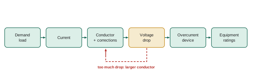
| Link | What you decide | Lesson |
|---|---|---|
| Demand load | Calculated load in W or VA by the Section 8 method for the occupancy | 3, 4, 5 |
| Current | Divide by the voltage, with √3 for three-phase | 1, 2 |
| Conductor | Ampacity at least the current (or 125% where the rules require), after corrections | 6, 10 |
| Voltage drop | Within 3% for the feeder or branch, 5% total | 7 |
| Overcurrent device | Standard rating protecting the conductor, considering continuous loading | 6, 9, 10 |
| Equipment | Service equipment, panel and breaker ratings, including interrupting rating | 9 |
Example 1: Aspen Ridge with its basement suite
In lesson 4, Aspen Ridge gained a basement suite. The combined load before heating and cooling was 32 825 W. The house has 12 kW of baseboards upstairs and the suite adds 6 kW, so the total heating is 18 kW; the 5 kW air conditioner is not interlocked. The EV charger stays in the main dwelling load. Now finish the calculation and size the service.
Worked problem
Completing the Aspen Ridge load
Add heating and cooling to the 32 825 W combined load and find the service current at 240 V.
Show solution
- Heating, 18 kW with Section 62 factors: 10 000 + 0.75 × 8000 = 16 000 W.
- Air conditioning, not interlocked: 5000 W.
- Calculated load: 32 825 + 16 000 + 5000 = 53 825 W.
- Current: 53 825 / 240 = 224.3 A.
Answer: 53 825 W, 224.3 A: the existing 200 A service is too small.
Because 224.3 A exceeds the existing 200 A service, the conversion needs a service upgrade, which is common when suites are added. Priya proposes two options to the owners. The first is a 400 A service with a main panel and a suite subpanel, which handles any future additions. The second is to install an energy management system for the EV charger, which the 2024 Code's Section 8 and Section 86 rules allow to reduce the load counted for EV supply equipment, and keep the load within a 225 A or 250 A service. The owners choose the 400 A service. For the exam, the point is that a calculated load slightly above a standard size is not rounded down: the service must meet or exceed the calculated load.
Worked problem
Service conductors (illustrative values)
A 400 A residential service uses aluminum conductors. Suppose, after checking the dwelling service provisions and the aluminum table in your Code, a conductor with an ampacity of at least 400 A at 75 °C is needed. The run from the meter base to the panel is 3 m, so voltage drop is negligible. What remains to check?
Show solution
- Conductor ampacity at least 400 A at the 75 °C termination limit (look up the size in the aluminum table).
- Voltage drop: negligible over 3 m.
- Service equipment rated at least 400 A, with an interrupting rating at or above the available fault current the utility provides.
- Panel spaces: Rule 8-108 sets the minimum number of branch circuit positions for the service size.
Answer: Conductor size from the table, equipment ratings, fault current and panel positions.
Example 2: Riverbend's parkade EV chargers
Two years after Riverbend Condos opened, the condo board asked Parkland Valley to add 24 Level 2 EV chargers in the parkade, one per stall, each 7.2 kW at 208 V. At full value that is 172.8 kW, more than the building's whole gas-heated service could take. The calculated load from lesson 4 was 243 361 W on an 800 A, 208 V service. Here, Rule 8-106 provides two tools: the recorded maximum demand over the last 12 months for the existing load, and an electric vehicle energy management system to limit the chargers' combined load.
Worked problem
Can the service take the chargers?
Riverbend's utility records show a 12-month maximum demand of 150 kVA. The service is 800 A at 208 V three-phase. An energy management system will limit the 24 chargers to a combined 60 kVA. Is there capacity?
Show solution
- Service capacity: 1.732 × 208 × 800 = 288 kVA.
- Existing recorded demand: 150 kVA. With the managed EV load: 150 + 60 = 210 kVA.
- Without management, at full value: 150 + 172.8 = 322.8 kVA, which exceeds the capacity.
- With management, 210 kVA is below 288 kVA, leaving margin; continuous loading limits still apply to the EV feeder and panel.
Answer: With the energy management system, yes: about 210 kVA against a capacity of 288 kVA.
The EV feeder itself must be sized for the load the management system allows, with the continuous-load rule from lesson 6 in mind, because EV charging runs for hours. If the system limits the parkade to 60 kVA at 208 V, the current is 60 000 / 360.3 = 166.5 A, and if the feeder breaker is not marked for 100% continuous operation, it must be rated at least 166.5 / 0.80 = 208 A, so a 225 A feeder breaker and conductors to match.
Example 3: the clinic feeder from the mall's 600 V distribution
The clinic transformer from lesson 9 is fed from the mall's 600 V distribution panel, 40 m away through the ceiling space. The transformer is 75 kVA with primary-only protection. Size the primary feeder and check its voltage drop.
Worked problem
Clinic primary feeder (illustrative values)
Rated primary current 72.2 A; conductors at least 125%: 90.3 A. The feeder runs 40 m in conduit with three current-carrying conductors at normal ambient. Suppose a copper conductor with a 75 °C ampacity of 100 A and a resistance of about 1.0 Ω/km is chosen. Check the voltage drop at full transformer load.
Show solution
- Ampacity 100 A ≥ 90.3 A: adequate (no corrections needed for three conductors at 30 °C).
- Voltage drop: 1.732 × 40 × 72.2 × 1.0 / 1000 = 5.0 V.
- As a share of 600 V: 0.83%, well within 3%.
- Primary device: up to 125% of 72.2 A, so 90 A, or the next standard size where the rule allows, which the 100 A conductor also covers.
Answer: The 100 A conductor works; voltage drop is under 1%.
Then the secondary: conductors of at least 260.3 A from the transformer to the clinic panel, a short run, and the panel's main breaker. The panel must be rated for the available fault current of about 6 kA from lesson 9, and its breakers must have an interrupting rating to match.
Example 4: Hartley Farms main service
Hartley Farms' original service was 200 A at 120/240 V single-phase, which had been fine for the house and shop. The new grain drying system brought three-phase motors, a dryer burner blower and a lot of aeration. The utility extended three-phase to the farm, and Parkland Valley installed a new 347/600 V three-phase service for the farm buildings, keeping the house on its own single-phase service. Farm loads are calculated as an occupancy with specific loads: the motor loads by the Section 28 feeder method, plus heating and lighting.
Worked problem
The farm buildings' service (illustrative values)
Motor control centre: 57.7 A minimum ampacity (from lesson 10). A 25 kVA single-phase transformer for the shop: rated primary current 41.7 A. Yard and building lighting: 8 kW at 347 V, continuous. Bin yard subpanel: 80 A at 240 V single-phase, fed through the shop transformer and so already inside its 25 kVA. Find the service current at 600 V three-phase.
Show solution
- Motor control centre: 57.7 A on all three lines.
- Shop transformer: 41.7 A on two lines; for a quick total, convert to kVA: 25 kVA.
- Lighting: 8 kW, continuous, balanced across the three phases: 8000 / 1039 = 7.7 A per line; for continuous loading use 125%: 9.6 A.
- Approximate total per line: 57.7 + 25 000 / 1039 + 9.6 = 57.7 + 24.1 + 9.6 = 91.4 A (treating the single-phase transformer load as spread evenly, which is an approximation).
- A 100 A service would be tight; Parkland Valley installed 200 A to allow for a second dryer the farm plans.
Answer: About 91 A per line; a 200 A service chosen for growth.
That example contains a simplification worth noticing: a single-phase load on a three-phase system does not spread evenly. A careful calculation puts the 41.7 A on the two lines it actually uses, which makes those lines heavier than the third. Exams usually tell you which approach to take; where they do not, the worst line governs.
The neutral
Every example above sized the line conductors. The neutral of a service or feeder can sometimes be smaller, because it carries only the unbalanced current, but the Code limits how much smaller and lists loads that do not qualify for a reduction. Electric ranges and dryers on 120/240 V circuits put some current on the neutral but much less than on the lines, while non-linear loads such as electronic equipment, LED drivers and EV chargers with switching power supplies can put more on the neutral than on any line, and for those no reduction is permitted and an increase may be needed. The rule in Section 4 on neutral conductor sizing sets out how to calculate the maximum unbalanced load and when the neutral may be reduced.
For the exam, the safe habits are these. Size the neutral equal to the line conductors unless the question asks you to apply the reduction. If it does, calculate the maximum unbalanced load as the rule directs, check whether any of the loads are excluded from a reduction, and never go below the minimum the rule sets in relation to the bonding requirements. At Riverbend, with electric baseboards and ranges on 208 V, the neutral reduction would have been allowed for much of the load; with the EV chargers added, the board's engineer kept the parkade feeder neutral full size.
Continuous loads, dwellings and the 80% rule
One question comes up in every example: is the load continuous, and does the 80% limit of Rule 8-104 apply? For single dwellings and apartments calculated by the Section 8 dwelling methods, the Code says the calculated load is not treated as continuous for that rule, because the demand factors already reflect diversity. For other occupancies, decide by the nature of the load: lighting in a store, EV charging, process loads and heating are usually continuous. Equipment marked for 100% continuous operation may carry its full rating; otherwise, size at 125% of the continuous load.
import math

def three_phase_amps(kva, volts):
    return kva * 1000 / (math.sqrt(3) * volts)

def capacity_kva(amps, volts, phases=3):
    return (math.sqrt(3) if phases == 3 else 1) * volts * amps / 1000

# Example 2: Riverbend EV chargers
cap = capacity_kva(800, 208)
print(f'Riverbend capacity {cap:.0f} kVA; managed {150 + 60} kVA; unmanaged {150 + 24 * 7.2:.1f} kVA')
ev = three_phase_amps(60, 208)
print(f'EV feeder {ev:.1f} A, breaker at 125%: {ev / 0.8:.0f} A')

# Example 3: clinic primary feeder voltage drop
vd = math.sqrt(3) * 40 * 72.2 * 1.0 / 1000
print(f'Clinic feeder drop {vd:.1f} V = {vd / 600:.2%}')Riverbend capacity 288 kVA; managed 210 kVA; unmanaged 322.8 kVA EV feeder 166.5 A, breaker at 125%: 208 A Clinic feeder drop 5.0 V = 0.83%
A checklist for complete questions
After the four examples, the study group writes a checklist for complete service and feeder questions, and Priya tapes it into the red tab of her code book. Identify the occupancy and the method. Calculate the load, writing every line. Decide whether the load is continuous. Convert to current at the right voltage. Choose the conductor from the right table and column with corrections, and limit it to the termination column. Check voltage drop. Choose the overcurrent device, protecting the conductor. Check equipment ratings, including interrupting rating. Then do Denise's three checks: units, size and direction.
Tyler, watching the group work through these, observes that every step is something he has seen on the job, just never written down in one place. Denise tells him that is exactly what a master electrician is: the person who writes it down, gets the permit and signs for it.
Common mistakes
MistakeRounding a calculated load down to the existing service size.
InsteadThe service must meet or exceed the calculated load; upgrade or reduce the load.
MistakeAdding EV chargers at full value when a management system is installed.
InsteadUse the load the energy management system allows, as Section 8 and Section 86 permit.
MistakeTreating a single-phase load on a three-phase service as evenly spread without saying so.
InsteadIt loads two lines; the worst line governs unless the question says to approximate.
MistakeApplying the 80% continuous rule to a dwelling calculated load.
InsteadSection 8 dwelling calculations are not treated as continuous for Rule 8-104.
MistakeSkipping voltage drop on a short service run without saying why.
InsteadState that the run is short and the drop negligible, so the examiner sees you checked.
Summary and key terms
- Service and feeder sizing is a chain: load, current, conductor, voltage drop, protection, equipment.
- A calculated load above a standard size means the next size up, an upgrade or a load-management solution.
- Rule 8-106 allows recorded 12-month demand for existing loads and managed EV loads.
- Continuous non-dwelling loads need protection rated at 125% unless equipment is marked for 100% operation.
- Check fault current and interrupting ratings at every panel.
- Energy management system
- A control system that limits the combined load of equipment such as EV chargers.
- Service capacity
- The apparent power a service can deliver at its rated current.
- Calculated load
- The demand load found by the Code's method for the occupancy.
- Branch circuit position
- A space in a panelboard for a branch circuit overcurrent device.
- Available fault current
- The current that would flow in a bolted fault at a point in the system.
Practice problems
Work each problem on paper first, then reveal the answer to check.
A dwelling calculated load is 50 400 W. What is the current at 240 V?
Show answer
210 A, so a service larger than 200 A is needed.
Capacity of a 600 A, 600 V three-phase service in kVA?
Show answer
1.732 × 600 × 600 = 623.5 kVA.
A managed EV load of 40 kVA at 208 V three-phase: breaker rating at 125%?
Show answer
40 000 / 360.3 = 111 A; 111 / 0.8 = 139 A, so 150 A.
A 50 m, 600 V feeder carrying 60 A on 1.6 Ω/km copper: drop?
Show answer
1.732 × 50 × 60 × 1.6 / 1000 = 8.3 V, 1.4%.
Lesson quiz · 5 questions
Score 60% or more to complete this lesson.
Create a free account to save your progress, take quizzes and earn a certificate.