
MELC-102 · Lesson 10 of 12 · 31 min
Motor branch circuit calculations
▶ Video coming soon A video version of this lesson is on the way.
Motor circuits are where Marcus is most at home and where many residential electricians feel least sure. They are also among the most heavily tested calculations on master exams, because a motor circuit combines several separate sizing decisions, each with its own rule: the conductors, the short-circuit and ground fault protection, the overload protection and the disconnecting means. Each is based on the motor's full-load current, and each uses a different multiple of it. Get the full-load current right and keep the multipliers straight, and motor questions become routine.
The motor rules are in Section 28 of the CE Code. This lesson covers the full-load current tables, conductor sizing for one motor and for several motors, the overcurrent protection table, overload protection and disconnecting means, with the Hartley Farms grain dryer as the example. Section 28's tables are Code content and are not reproduced here; worked examples use illustrative table values, clearly labelled. Lesson 1 of MELC-105 goes deeper into the motor rules themselves.
Start with the table full-load current
For sizing conductors and short-circuit protection, the Code tells you to use the full-load current from its motor tables, not the current on the motor's nameplate. There is a table for three-phase AC motors and one for single-phase AC motors, giving full-load currents by horsepower or kilowatt rating and voltage. The table values are typical for motors of that size and voltage, so the circuit does not have to be redesigned if the motor is replaced with a different make. Overload protection is the exception: it is based on the nameplate full-load current, because it protects that particular motor from overheating.
| Sizing decision | Based on | Commonly applied multiplier |
|---|---|---|
| Branch circuit conductors (one motor) | Table full-load current | 125% |
| Short-circuit and ground fault protection | Table full-load current | Maximum % from the protection table, by device type |
| Overload protection | Nameplate full-load current | 125% for motors with a service factor of 1.15 or more or a marked temperature rise of 40 °C or less; otherwise 115% |
| Disconnecting means | Table full-load current | At least 115% (ampere rating), or a horsepower-rated switch |
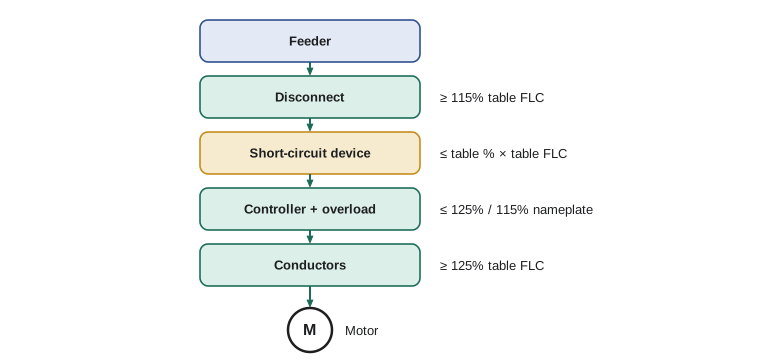
Conductors for one motor
Rule 28-106 requires the conductors supplying a single motor to have an ampacity of at least 125% of the motor's full-load current from the table. The extra 25% covers the motor running slightly above its rated current, which motors do, and gives margin for the starting duty. For motors with unusual duty cycles, such as intermittent or short-time duty, the rule allows different multipliers; exam questions usually say continuous duty, and you use 125%.
Worked problem
The aeration fan motor (illustrative table value)
A 25 hp, 600 V three-phase aeration fan motor runs continuously. Suppose the three-phase motor table gives a full-load current of 27 A for that size and voltage. Find the minimum conductor ampacity.
Show solution
- Conductor ampacity ≥ 1.25 × 27 = 33.75 A (illustrative table value).
- Then size from the ampacity tables with corrections, as in lesson 6.
Answer: At least 33.75 A with this illustrative full-load current.
Conductors for several motors
A feeder supplying several motors needs an ampacity of at least 125% of the full-load current of the largest motor plus 100% of the full-load currents of all the others. The logic is that only one motor needs the 25% margin; the chance that every motor runs above its rating at once is small. If the feeder also supplies other loads, they are added according to their own rules. Rule 28-108 sets this out; check it in your Code, including how to handle motors that cannot run at the same time.
Worked problem
The dryer motor control centre (illustrative table values)
A small motor control centre at Hartley Farms supplies the 25 hp fan (27 A), a 10 hp auger (11 A), a 7.5 hp auger (9 A) and a 3 hp bucket elevator (3.9 A), all 600 V three-phase, with illustrative table currents as shown. Find the minimum feeder ampacity.
Show solution
- Largest motor at 125%: 1.25 × 27 = 33.75 A.
- Others at 100%: 11 + 9 + 3.9 = 23.9 A.
- Feeder ampacity ≥ 33.75 + 23.9 = 57.65 A.
Answer: At least 57.7 A with these illustrative full-load currents.
A common error is to apply 125% to every motor, which gives 64.4 A here and oversizes the feeder. Another is to apply 125% to the smallest motor or to none. Write the largest motor on its own line first.
Short-circuit and ground fault protection
The overcurrent device ahead of a motor circuit must let the motor start, which can draw six or more times its full-load current for several seconds, while still protecting the conductors against short circuits and ground faults. Because starting current is so much higher than running current, this device is usually rated well above the conductor ampacity, and the conductors are protected against overload by the separate overload device. The Code's protection table gives the maximum rating of the short-circuit device as a share of the table full-load current, with different multipliers for different device types: non-time-delay fuses, time-delay fuses, inverse-time circuit breakers and instantaneous-trip breakers.
Worked problem
Protecting the fan circuit (illustrative multiplier)
For the 25 hp fan with a table full-load current of 27 A, suppose the protection table allowed an inverse-time breaker of up to 250% of full-load current for this motor type. What is the maximum breaker rating?
Show solution
- Maximum = 2.50 × 27 = 67.5 A (illustrative multiplier).
- Choose a standard breaker not larger than this, unless the rule's provisions for the next size or for starting problems apply.
Answer: About 67.5 A maximum with this illustrative multiplier.
The rules recognise that a calculated maximum often falls between standard device ratings, and they give provisions for using the next size up in some situations and for going higher if the motor cannot start. These are exactly the details that exam questions test, so read them in your Code and note them on your lookup sheet. For a feeder supplying several motors, the feeder protection is based on the largest motor's maximum device rating plus the full-load currents of the others, so that the feeder device does not trip when the largest motor starts while the others run.
Worked problem
Feeder protection for the motor control centre (illustrative values)
With the illustrative values above, the fan's maximum branch device is 67.5 A. Find the maximum feeder device rating.
Show solution
- Largest motor's device: 67.5 A.
- Plus the others' full-load currents: 23.9 A.
- Maximum feeder device: 91.4 A; choose a standard rating not above it, applying the rule's provisions.
Answer: About 91 A maximum with these illustrative values.
Overload protection
Overload protection, usually a thermal or electronic overload relay in the motor starter, protects the motor and its conductors from sustained moderate overcurrent: a jammed auger, a failing bearing, a single-phasing supply. Rule 28-306 sets the maximum overload setting as a share of the motor's nameplate full-load current: 125% for motors with a marked service factor of 1.15 or more or a marked temperature rise of 40 °C or less, and 115% for other motors. The rule allows a somewhat higher setting if the motor cannot start or carry its load at the normal setting.
Worked problem
Setting the fan overload
The fan motor's nameplate shows 26 A full-load current and a service factor of 1.15. What is the maximum overload setting?
Show solution
- Service factor 1.15, so 125% applies.
- Maximum setting: 1.25 × 26 = 32.5 A, based on the nameplate current, not the table current.
Answer: 32.5 A.
Note the switch from table current to nameplate current. On the exam, a motor question that gives both values is testing whether you use each in the right place. Table current for conductors, short-circuit protection and disconnects; nameplate current for overloads.
Disconnecting means
Every motor needs a disconnecting means that can open all ungrounded conductors and is within sight of the motor and controller or can be locked open, as the rules in Section 28 describe. Its rating must be at least 115% of the table full-load current if it is rated in amperes, or it must be horsepower-rated for at least the motor's horsepower. A fused disconnect also serves as the short-circuit protection if its fuses are sized according to the protection table.
Worked problem
Fan disconnect
Minimum ampere rating of a disconnect for the fan motor with a table full-load current of 27 A?
Show solution
- 1.15 × 27 = 31.05 A, so a 60 A disconnect (the next common size above 31 A in the series used) or a horsepower-rated switch of at least 25 hp at 600 V.
Answer: At least 31.05 A, or horsepower-rated for 25 hp.
Starting current and voltage dip
A motor started across the line draws a locked-rotor current of roughly six times its full-load current until it reaches speed. On a long feeder, that current causes a voltage dip several times larger than the running voltage drop from lesson 7. If the fan's feeder drops 2% at running current, it may dip 10 to 12% at starting, enough to make lights flicker and contactors on other equipment drop out. That is why large motors are often started with reduced-voltage starters, soft starters or drives, and why the protection rules allow the short-circuit device to be rated so far above the running current.
At Hartley Farms, the original 25 hp fan was started across the line, and the farmhouse lights dimmed every time it started. When the fan was replaced, Parkland Valley fitted a soft starter, which ramps the voltage up over a few seconds and roughly halves the starting current. The dimming stopped, and the utility's complaint about flicker on the rural line went away with it.
Variable-frequency drives
More and more motors at farms and in buildings are run through variable-frequency drives, which control speed by changing the frequency and voltage supplied to the motor. For a motor on a drive, the conductors and protection on the supply side are based on the drive's rated input current rather than the motor table current, and the drive often provides the motor's overload protection electronically. Section 28 has specific rules for adjustable-speed drives; read them in your Code, because exam questions increasingly include a drive. The calculation pattern stays the same, with the drive's input current taking the place of the motor's full-load current where the rule says so.
Worked problem
An exam-style motor question
A 15 hp, 600 V three-phase continuous-duty motor has an illustrative table full-load current of 17 A and a nameplate full-load current of 16.4 A with a service factor of 1.0 and no marked temperature rise. It is protected by time-delay fuses, which suppose the protection table allows at up to 175% of full-load current. Find the conductor ampacity, the maximum fuse rating, the maximum overload setting and the minimum disconnect rating.
Show solution
- Conductors: 1.25 × 17 = 21.25 A.
- Fuses: 1.75 × 17 = 29.75 A maximum (illustrative multiplier).
- Overload: service factor 1.0, so 115% of nameplate: 1.15 × 16.4 = 18.86 A.
- Disconnect: 1.15 × 17 = 19.55 A, or horsepower-rated for 15 hp at 600 V.
Answer: 21.25 A conductors; fuses up to about 29.75 A; overload up to 18.86 A; disconnect at least 19.55 A.
Single-phase motors
Single-phase motors at Hartley Farms run grain cleaners, small augers, shop air compressors and well pumps. The method is identical, using the single-phase motor table for full-load current. A 2 hp, 230 V single-phase compressor motor with an illustrative table current of 12 A needs conductors of at least 15 A ampacity, overload protection based on its nameplate, and a disconnect of at least 13.8 A or horsepower-rated. Because single-phase full-load currents are high for their horsepower, a common exam trap is to look up the motor in the three-phase table by mistake.
Putting it on one page
Priya builds a one-page motor worksheet for the exam: the motor's horsepower, voltage and phase at the top; the table full-load current and nameplate current on the next line; then four boxes for conductor, short-circuit device, overload and disconnect, each with its multiplier and the rule number written in. For several motors, a fifth box for the feeder, with the largest motor circled. The worksheet turns a five-part question into five one-line calculations.
def motor_circuit(table_flc, nameplate_flc, sf_115=True, max_device_pct=2.5):
    # Illustrative maximum device multiplier: look up your Code's table for the device type.
    return {
        'conductor ampacity >=': round(1.25 * table_flc, 2),
        'short-circuit device <=': round(max_device_pct * table_flc, 1),
        'overload setting <=': round((1.25 if sf_115 else 1.15) * nameplate_flc, 2),
        'disconnect amps >=': round(1.15 * table_flc, 2),
    }

def feeder(table_flcs, largest_device):
    largest = max(table_flcs)
    others = sum(table_flcs) - largest
    return round(1.25 * largest + others, 2), round(largest_device + others, 1)

print(motor_circuit(27, 26))
amp, dev = feeder([27, 11, 9, 3.9], largest_device=67.5)
print('feeder ampacity >=', amp, ' feeder device <=', dev){'conductor ampacity >=': 33.75, 'short-circuit device <=': 67.5, 'overload setting <=': 32.5, 'disconnect amps >=': 31.05}
feeder ampacity >= 57.65 feeder device <= 91.4Common mistakes
MistakeUsing nameplate current for conductor sizing.
InsteadConductors, short-circuit protection and disconnects use the table full-load current.
MistakeUsing table current for overload settings.
InsteadOverloads use the nameplate full-load current.
MistakeApplying 125% to every motor on a feeder.
InsteadOnly the largest motor takes 125%; the others are at 100%.
MistakeExpecting the short-circuit device to protect against overload.
InsteadIt is sized for starting current; the overload relay protects against overload.
MistakeLooking up a single-phase motor in the three-phase table.
InsteadUse the table for the motor's phase and voltage.
Summary and key terms
- Conductors, short-circuit protection and disconnects use the Code's table full-load current; overloads use the nameplate.
- Single motor conductors: at least 125% of full-load current (Rule 28-106).
- Several motors: 125% of the largest plus 100% of the others (Rule 28-108).
- Short-circuit device maximums come from the protection table by device type, with provisions for the next size and starting.
- Overloads: up to 125% or 115% of nameplate current (Rule 28-306); disconnects at least 115% or horsepower-rated.
- Full-load current
- The current a motor draws at rated load; for most sizing, taken from the Code's table.
- Service factor
- A multiplier on a motor's rating indicating permissible continuous overload.
- Overload relay
- A device in the starter that trips on sustained overcurrent to protect the motor.
- Inverse-time breaker
- A breaker that trips faster as the current gets larger.
- Motor control centre
- An assembly of motor starters and protective devices in one enclosure.
Practice problems
Work each problem on paper first, then reveal the answer to check.
Table FLC 40 A: minimum conductor ampacity?
Show answer
50 A.
Motors with table FLC 40, 20 and 10 A on one feeder: minimum feeder ampacity?
Show answer
1.25 × 40 + 30 = 80 A.
Nameplate FLC 18 A, service factor 1.0, temperature rise not marked: maximum overload setting?
Show answer
1.15 × 18 = 20.7 A.
Table FLC 40 A: minimum disconnect ampere rating?
Show answer
46 A.
Lesson quiz · 5 questions
Score 60% or more to complete this lesson.
Create a free account to save your progress, take quizzes and earn a certificate.