
MELC-105 · Lesson 5 of 12 · 19 min
Hazardous locations: the zone and class systems in Section 18
▶ Video coming soon A video version of this lesson is on the way.
Hazardous locations are the topic Priya is least confident about, and she is not alone: for a contractor who mostly wires houses and small commercial buildings, Section 18 can feel like a foreign language. Yet every master exam has questions on it, and agricultural work brings it to the door. A grain elevator handles combustible dust, a farm fuel station dispenses gasoline and diesel, a propane-fired dryer has gas piping and a regulator, and a seed-cleaning plant fills the air with fine organic dust. Understanding how locations are classified, and what that classification means for the wiring, is part of being the person who signs the permit.
This lesson covers the principles: what makes a location hazardous, the zone system used in Section 18, the older class and division system kept in Annex J18, gas and dust groups, temperature codes, equipment protection levels and protection methods, and the general installation principles of sealing and wiring methods. It does not attempt the detailed design of a hazardous installation, which needs the full Code, the relevant standards and often an engineer's area classification drawing. Code text and tables are not reproduced; use your own 2024 CE Code, where Section 18 and Annex J18 had substantially revised sealing requirements in this edition.
What makes a location hazardous
A location is hazardous when flammable gases or vapours, combustible dusts, or ignitable fibres are, or may be, present in the air in quantities enough to produce an explosive or ignitable mixture. Three things are needed for an explosion: fuel in the right concentration, oxygen from the air, and an ignition source. Electrical equipment is an ignition source through sparks from contacts, arcs from faults and hot surfaces. The Code's approach is to classify each location by how likely an explosive atmosphere is and how long it lasts, then require electrical equipment and wiring whose protection matches that likelihood.
Classification is not the electrician's job alone. The owner, often with an engineer or a fire protection specialist, prepares the area classification, usually as a drawing with zones marked around each source of release. Codes and standards such as the National Fire Code and industry practices guide it. The electrician's job is to select and install equipment that suits the classification, and the inspector's job is to verify it. On an exam, a question will usually give you the classification and ask about equipment, or describe a situation and ask what classification is likely.
The zone system for gases and vapours
Section 18 uses the zone system, which comes from international practice. For flammable gases and vapours, there are three zones. Zone 0 is a location where an explosive atmosphere is present continuously or for long periods, such as the vapour space inside a fuel tank. Zone 1 is where an explosive atmosphere is likely to occur in normal operation, such as near a vent or an open fill point. Zone 2 is where an explosive atmosphere is not likely in normal operation and, if it does occur, will exist only for a short time, such as around a pipe flange that might leak only if a gasket fails. Locations outside these zones are non-hazardous for the purpose of the rules.
For combustible dusts, there are three parallel zones. Zone 20 is where a combustible dust cloud is present continuously or frequently, such as inside a grain leg or a dust collector. Zone 21 is where a dust cloud is likely in normal operation, such as near a bin's loading spout. Zone 22 is where a dust cloud is not likely in normal operation and would exist only briefly, which often includes the areas around equipment where dust layers might be disturbed. Dust layers matter as well as clouds: a layer of grain dust on a motor can ignite from the motor's surface heat and then spread fire or raise a cloud that explodes.
| Zone | Material | Likelihood of explosive atmosphere | Farm example (classification is for illustration only) |
|---|---|---|---|
| Zone 0 | Gas or vapour | Continuous or long periods | Inside the vapour space of a gasoline storage tank |
| Zone 1 | Gas or vapour | Likely in normal operation | Close to a tank vent or fill point |
| Zone 2 | Gas or vapour | Not likely; short duration if it occurs | Around a propane regulator or valve assembly |
| Zone 20 | Combustible dust | Continuous or frequent cloud | Inside a grain leg or dust collector |
| Zone 21 | Combustible dust | Likely in normal operation | Near the loading spout of a grain bin |
| Zone 22 | Combustible dust | Not likely; short duration if it occurs | The general area of a grain-handling building with good housekeeping |
The class and division system in Annex J18
Before the zone system, Canada used classes and divisions, as the US still does in most installations. Class I covers gases and vapours, Class II covers combustible dusts and Class III covers ignitable fibres and flyings, such as cotton lint. Each class has Division 1, where the hazard exists in normal operation, and Division 2, where it exists only in abnormal conditions. The CE Code keeps the class and division rules in Annex J18 so that existing installations can be maintained and extended under the system they were built with, and so that equipment marked only for classes and divisions can be used where the rules allow.
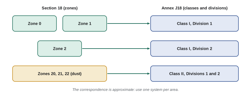
The two systems do not map exactly. Roughly, Zone 0 and Zone 1 together correspond to Class I, Division 1, and Zone 2 corresponds to Class I, Division 2; the dust zones correspond roughly to Class II divisions. But the boundaries and the equipment rules differ, so you cannot mix the two systems casually in one area. On an exam, read whether the question describes a zone or a division and open the right part of the Code. Priya tabs Section 18 in green with the rest of the supplementary sections, and Annex J18 in a lighter green right behind it.
Groups and temperature codes
Not all flammable gases are equally easy to ignite. The zone system divides gases into groups by how easily a flame passes through a narrow gap and how much energy ignites them: Group IIA includes propane and gasoline vapour, Group IIB includes ethylene, and Group IIC includes hydrogen and acetylene, the most easily ignited. Equipment marked IIC is suitable for IIB and IIA atmospheres, but not the other way round. Dusts are grouped too: IIIA for combustible flyings, IIIB for non-conductive dusts such as grain and flour, and IIIC for conductive dusts such as some metal dusts.
Every flammable material also has an autoignition temperature, the surface temperature at which it ignites without a spark. Equipment is marked with a temperature code from T1 to T6 showing its maximum surface temperature, from 450 °C for T1 down to 85 °C for T6. The equipment's temperature code must be below the autoignition temperature of the material present. For dusts, the equipment is marked with its maximum surface temperature directly, and that must be below both the cloud ignition temperature and the layer ignition temperature of the dust, with margins set by the rules and standards. Grain dust layers can ignite at temperatures well below what a cloud needs, which is why dust layer thickness matters.
Worked problem
Can a T3 motor be used in a propane area?
A Zone 2 area around a propane vaporizer at the dryer needs a motor for a ventilation fan. The motor available is marked Ex nA IIA T3. Propane's autoignition temperature is roughly 450 °C. Is the temperature code suitable?
Show solution
- T3 means a maximum surface temperature of 200 °C.
- 200 °C is well below propane's autoignition temperature of about 450 °C.
- The group IIA marking also suits propane, and Ex nA is a protection method suitable for Zone 2.
Answer: Yes, on temperature, group and protection method, subject to the area classification drawing and the rest of the rules.
Equipment protection levels and protection methods
Equipment for hazardous locations is designed so that it cannot ignite the surrounding atmosphere. Different designs, called protection methods or types of protection, do this in different ways. Flameproof enclosures (marked d) contain an internal explosion and cool the escaping gases so that the flame cannot reach the outside. Increased safety (e) prevents sparks and hot surfaces by careful design of connections and windings. Intrinsic safety (i) limits the energy in a circuit so that even a spark cannot ignite the atmosphere. Pressurization (p) keeps the enclosure at positive pressure with clean air. Encapsulation (m), oil immersion (o), powder filling (q) and the non-sparking type n complete the common list. Dust protection uses protection by enclosure (t), along with intrinsic safety, pressurization and encapsulation.
Each piece of equipment also has an equipment protection level that says how safe it is: Ga, Gb and Gc for gas, with Ga the highest, and Da, Db and Dc for dust. The rules match protection levels to zones: Zone 0 needs Ga, Zone 1 needs Gb or better, and Zone 2 needs Gc or better, with the dust zones following the same pattern. This is the cleanest way to answer most equipment selection questions on an exam: identify the zone, find the protection level it requires, and check the equipment marking.
| Zone | Minimum equipment protection level | Typical protection methods at that level (examples) |
|---|---|---|
| Zone 0 | Ga | Intrinsic safety ia, encapsulation ma |
| Zone 1 | Gb | Flameproof d, increased safety e, intrinsic safety ib, pressurization px or py |
| Zone 2 | Gc | Type n, intrinsic safety ic, pressurization pz |
| Zone 20 | Da | Intrinsic safety ia, encapsulation ma, enclosure ta |
| Zone 21 | Db | Enclosure tb, intrinsic safety ib, pressurization |
| Zone 22 | Dc | Enclosure tc, intrinsic safety ic |
Wiring methods and sealing
The wiring between hazardous-location equipment matters as much as the equipment itself. Section 18 specifies acceptable wiring methods for each zone, which in practice means threaded rigid metal conduit, certain armoured and metal-sheathed cables with suitable fittings, and in the lower-hazard zones a wider choice of cable types. Fittings and cable glands must themselves be approved for the zone and protection method. Flexible connections to vibrating equipment such as motors have their own permitted methods.
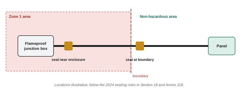
Seals are required where conduits enter certain enclosures and where they pass from a hazardous location into a less hazardous or non-hazardous one, to stop gas, vapour or flame travelling through the conduit system. Seal fittings are filled with a compound after the conductors are pulled, with damming fibre to hold the compound, and the compound depth and the distance from the enclosure are set by the rules and the fitting's instructions. The 2024 edition substantially revised the sealing requirements in Section 18 and Annex J18, so anyone who learned sealing under an older edition should read the current rules closely. Exams test sealing more than almost any other installation detail.
Hazardous locations on the farm
At Hartley Farms, the area classification for the new grain-handling building was prepared by the bin supplier's engineer, as part of the building's fire safety plan, and marks the inside of the leg and dust collector as Zone 20, the areas around the bin loading spouts as Zone 21, and the general building interior as Zone 22. The propane vaporizer pad outside is classified Zone 2 within a stated radius. Priya's job is to check that every motor, light, switch and junction box matches its zone and that the wiring and seals follow Section 18. She makes a schedule listing each item, its location, the zone, the required protection level, the equipment marking and the rule numbers she used.
She also notes Section 20, which deals with specific occupancies such as fuel dispensing, garages and bulk storage plants, and gives classified areas around dispensers and vents directly rather than leaving them to an engineer's drawing. The farm's gasoline and diesel dispensing station falls under it. On exams, a question about a gas station or a vehicle repair garage is usually a Section 20 question, not a general Section 18 one.
Common mistakes
MistakeMixing zone-marked and division-marked equipment in one area without checking the rules.
InsteadUse one system per area and follow the rules for equipment marked under the other system.
MistakeChoosing equipment by protection method without checking the protection level.
InsteadMatch the equipment protection level to the zone: Ga, Gb, Gc and Da, Db, Dc.
MistakeChecking only the cloud ignition temperature for dust.
InsteadDust layers ignite at lower temperatures; check both.
MistakeAssuming IIA equipment suits hydrogen.
InsteadIIC equipment suits all gas groups; IIA suits only the least easily ignited.
MistakeApplying sealing rules from an older edition.
InsteadThe 2024 edition substantially revised sealing in Section 18 and Annex J18.
Summary and key terms
- A hazardous location may contain flammable gas, vapour, dust or fibres in ignitable amounts; electrical equipment is controlled as an ignition source.
- Section 18 uses Zones 0, 1 and 2 for gases and vapours and Zones 20, 21 and 22 for dusts; Annex J18 keeps classes and divisions.
- Gas groups IIA, IIB and IIC and dust groups IIIA, IIIB and IIIC, with temperature codes T1 to T6, guide equipment selection.
- Equipment protection levels Ga, Gb, Gc and Da, Db, Dc match the zones; protection methods include d, e, i, p, m, o, q, n and t.
- Wiring methods and seals are specified by zone; the 2024 edition revised the sealing rules; Section 20 covers specific occupancies such as fuel dispensing.
- Area classification
- The determination, usually on a drawing, of the zones around sources of flammable material.
- Autoignition temperature
- The temperature at which a material ignites without a spark or flame.
- Equipment protection level
- A rating of how safe equipment is in an explosive atmosphere: Ga, Gb, Gc, Da, Db or Dc.
- Flameproof enclosure
- An enclosure that contains an internal explosion and prevents it from igniting the surroundings.
- Intrinsic safety
- A protection method that limits circuit energy so it cannot ignite the atmosphere.
Practice problems
Work each problem on paper first, then reveal the answer to check.
Which zone describes a gas atmosphere likely in normal operation?
Show answer
Zone 1.
A T4 device has what maximum surface temperature?
Show answer
135 °C.
Which equipment protection level is needed in Zone 21?
Show answer
Db or better.
Which part of the Code keeps the class and division system?
Show answer
Annex J18.
Lesson quiz · 5 questions
Score 60% or more to complete this lesson.
Create a free account to save your progress, take quizzes and earn a certificate.