
MELC-105 · Lesson 10 of 12 · 26 min
Solar photovoltaic and energy storage systems in Section 64
▶ Video coming soon A video version of this lesson is on the way.
Solar panels on machine sheds and battery systems in garages have gone from novelty to routine in Alberta, and Section 64 has changed with them. The 2024 edition made major revisions to the rules for renewable energy and energy storage systems, including a new subsection for residential occupancies and updated photovoltaic requirements. That makes Section 64 one of the most likely sources of new exam questions on the current edition, and one of the riskiest places to rely on what you learned under an older one. The good news is that most questions come down to a few concepts: the parts of a system, maximum DC voltage and how cold weather raises it, conductor sizing from short-circuit current, disconnects and rapid shutdown, storage installation, and how the system connects to the utility under Section 84.
This lesson works through those concepts with the Hartley Farms project from MELC-101: a 40 kW photovoltaic array on the roof of the new grain-handling building, a battery energy storage system in the shop, and a utility-interactive connection to the farm's service. As in every MELC lesson, rules are explained in plain words and every value that would come from a Code table or a manufacturer's data sheet is labelled illustrative. Read Section 64 and Section 84 in your own 2024 CE Code, together with your utility's interconnection requirements.
Parts of a photovoltaic system
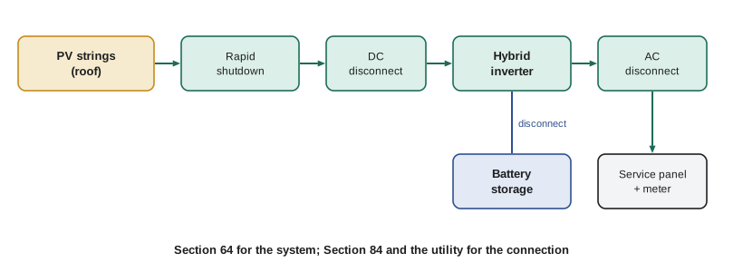
A photovoltaic module converts sunlight into DC electricity. Modules are connected in series into strings to raise the voltage, and strings are connected in parallel to raise the current. The DC from the array goes to an inverter, which converts it to AC at the voltage and frequency of the building's supply. Utility-interactive inverters synchronize with the utility and shut down automatically when the utility fails, so they cannot backfeed a dead line; this anti-islanding function is part of their certification. Systems with storage add batteries, a battery management system and often a hybrid inverter that can charge the batteries and supply backup loads during an outage. Microinverters and DC optimizers at each module are alternatives to a central string inverter.
Section 64 covers the installation of these systems: conductors and wiring methods for the DC side, overcurrent protection, disconnecting means, rapid shutdown of conductors on buildings, grounding and bonding, marking, and the installation of storage. Section 84 covers the connection of any power production source to the utility supply, including PV and storage, and the utility's own requirements add more. Priya tabs Sections 64 and 84 together in green.
Maximum DC voltage and cold weather
A PV module's open-circuit voltage rises as its temperature falls. On a clear, cold January morning in central Alberta, with the sun just up and the cells at minus 35 °C, a string's open-circuit voltage can be well above its rated value at the standard test temperature of 25 °C. The Code requires the maximum system voltage to be calculated for the lowest expected ambient temperature, using either the module manufacturer's temperature coefficient or a correction factor table in the Code, and that voltage must not exceed the ratings of the modules, inverter, conductors and disconnects. Exceeding the inverter's maximum input voltage can destroy it, so string length is limited by the cold-weather voltage.
Worked problem
Longest string for the Hartley inverter (illustrative module data)
Each module has an open-circuit voltage of 49.5 V at 25 °C and a temperature coefficient of −0.27% per °C. The design minimum temperature is −40 °C and the inverter's maximum DC input voltage is 1000 V. How many modules can be in one string?
Show solution
- Temperature difference: −40 − 25 = −65 °C.
- Voltage factor: 1 + (−0.0027 × −65) = 1 + 0.1755 = 1.1755.
- Cold open-circuit voltage per module: 49.5 × 1.1755 = 58.19 V.
- Maximum modules: 1000 / 58.19 = 17.2, so 17 modules per string.
Answer: 17 modules, giving about 989 V on the coldest morning, with these illustrative values.
Using the standard 25 °C voltage would allow 20 modules and produce about 1164 V in deep cold, which is why the cold correction is one of the most tested PV calculations. If the manufacturer gives a temperature coefficient, use it; if not, the Code's correction factor table applies.
Conductor sizing on the DC side
PV source circuits carry current up to the modules' short-circuit current, and on bright days with snow or cloud-edge reflections, irradiance can exceed the standard test value, so the current can exceed the rated short-circuit current for periods long enough to matter. The rules therefore size PV source and output circuit conductors from the short-circuit current with multipliers that account for both the irradiance and the continuous nature of the current. A common way to express this is two factors of 125%, giving 156% of the short-circuit current; confirm how your edition states it, because the 2024 revisions changed some PV requirements. Conductors on rooftops are also exposed to high temperatures, so ampacity corrections for ambient and for conduit on or near the roof apply.
Worked problem
Source circuit conductors (illustrative values)
Each Hartley module has a short-circuit current of 13.9 A. A string's conductors run in a raceway on the roof. Using two factors of 125% as an illustration, what minimum current must the conductors carry before ambient corrections?
Show solution
- Short-circuit current of the string: 13.9 A (strings are series-connected, so current is that of one module).
- First factor for irradiance: 1.25 × 13.9 = 17.38 A.
- Second factor for continuous duty: 1.25 × 17.38 = 21.72 A.
Answer: About 21.7 A before correcting for rooftop ambient temperature and raceway fill.
Where three or more strings are paralleled, a fault in one string can be fed by the others, so string fuses or overcurrent protection may be required on each string, sized from the short-circuit current as the rules and the module listing specify. Two strings in parallel usually do not need string fuses, because one string cannot feed enough current into the other to exceed the module's series fuse rating. Exams test both the fuse rule and the parallel string count.
Disconnects and rapid shutdown
The rules require disconnecting means for the PV system: on the DC side at the inverter, on the AC side between the inverter and the building's distribution, and for the storage system, each readily accessible and clearly marked. The marking requirements are detailed, because firefighters and electricians need to know at a glance that a building has a second source and where to shut it off. A directory at the service showing the location of every source disconnect is typical.
Rapid shutdown addresses a hazard unique to PV: the modules keep producing voltage whenever light falls on them, so turning off the inverter does not make the rooftop conductors safe. The rules require PV systems on buildings to have a rapid shutdown function that reduces the voltage of conductors on or in the building to a safe level within a short time after it is initiated, typically by module-level electronics controlled by a switch at the service or by loss of utility power. Firefighters can then cut holes in the roof without meeting live DC conductors at high voltage. The details of the boundaries and voltage limits are exam material; read them in your Code.
| Function | What it does | Why exams ask about it |
|---|---|---|
| DC disconnect | Isolates the array from the inverter | Location and rating against maximum DC voltage |
| AC disconnect | Isolates the inverter from the building supply | Location and marking |
| Rapid shutdown | Reduces conductor voltage on the building after initiation | Boundaries, time limit and initiation method |
| String overcurrent protection | Protects strings from fault current fed by parallel strings | Number of parallel strings that triggers it |
| Source directory | Shows the location of every source and disconnect | Marking requirements at the service |
Energy storage systems
Battery energy storage systems store energy for later use, for backup during outages, for shifting solar energy into the evening, or for reducing peak demand charges. Most new systems use lithium-ion batteries, which store a lot of energy in a small space and can enter thermal runaway, a self-sustaining overheating that releases flammable gases and is very hard to extinguish, if damaged or badly managed. The 2024 revisions to Section 64 added requirements for storage, including a residential subsection that addresses where storage may be installed in a dwelling, limits on capacity in certain locations, separation from living spaces, protection from vehicle impact in garages, and disconnecting means. Fire codes and the product's listing add further requirements.
At Hartley Farms, the 60 kWh battery system goes in the shop, on a concrete floor away from the grain dust area, with the clearances given in the manufacturer's installation instructions, a disconnect at the battery cabinet and another at the inverter, and protection from the farm loader that parks nearby. Priya checks the battery cabinet's listing, the shop's classification under Section 22 for the dusty harvest season, and the fire separation the building code requires. She notes that a battery system in a farmhouse would fall under the new residential subsection, with tighter location rules.
Worked problem
How long can the battery run the backup loads? (illustrative values)
The battery has a usable capacity of 54 kWh. During an outage, the hybrid inverter supplies the farmhouse's essential loads, averaging 3.6 kW, at an inverter efficiency of 95%. How long can it run without solar input?
Show solution
- Energy delivered to loads: 54 × 0.95 = 51.3 kWh.
- Run time: 51.3 / 3.6 = 14.25 h.
Answer: About 14 hours, before any solar recharge, with these illustrative values.
Connecting to the utility under Section 84
A utility-interactive system connects to the building's electrical system and, through it, to the utility. Section 84 sets the rules for that interconnection, and the utility sets its own technical requirements and approval process. The connection can be on the supply side of the service disconnect, between the meter and the main breaker, or on the load side, through a breaker in a panelboard. Load-side connections raise a question about the panel's busbar: the busbar is protected by the main breaker from the utility side, but the inverter breaker adds current from the other direction, so the total could exceed the busbar's rating. The rules limit the sum of the overcurrent device ratings feeding the busbar to a stated share of its rating, and often require the inverter breaker to be at the opposite end of the bus from the main. The example below uses an illustrative 120% limit to show the method.
Worked problem
Can the inverter connect to the shop panel? (illustrative limit)
The shop panel has a 200 A busbar and a 200 A main breaker. The inverter's AC output current is 48 A, needing a 60 A breaker. Using an illustrative limit of 120% of busbar rating for the sum of supply breakers, is a load-side connection allowed?
Show solution
- Allowed sum: 1.20 × 200 = 240 A.
- Actual sum: 200 + 60 = 260 A, which exceeds 240 A.
- Options: reduce the main breaker, use a supply-side connection, or connect at a panel with a larger busbar.
Answer: Not with these values; Priya proposes a supply-side connection approved by the utility.
Grounding, bonding and arc-fault protection
PV module frames, racking and other exposed metal on the array must be bonded, because a fault inside a module or a damaged conductor could energize them. Racking systems are often listed for bonding, with bonding washers or clips that pierce the module frame's anodized coating; where they are not, separate bonding conductors are run. Whether the DC side of the system is grounded or ungrounded depends on the inverter: most modern transformerless inverters operate with an ungrounded array and include ground fault detection that stops the inverter and raises an alarm if a conductor faults to ground. The rules for each arrangement differ, so the inverter's documentation decides which rules you apply.
DC arcs are harder to extinguish than AC arcs, because DC current does not pass through zero every half cycle. A loose connector or a damaged conductor on a roof can sustain an arc that starts a fire. The rules require DC arc-fault protection for PV systems on or in buildings above a stated voltage, usually built into the inverter, which detects the electrical signature of an arc and shuts the system down. At Hartley Farms, the inverter's arc-fault and ground fault functions are listed on its data sheet, and Priya checks both against the rules before she approves the equipment submittal.
A PV string calculator
voc, beta, t_min, inv_max = 49.5, -0.0027, -40, 1000   # illustrative module and inverter data
isc = 13.9

factor = 1 + beta * (t_min - 25)
v_cold = voc * factor
n = int(inv_max // v_cold)
print('cold Voc per module', round(v_cold, 2), 'V')
print('max modules per string', n, '-> string Voc', round(n * v_cold, 1), 'V')
print('source circuit current (2 x 125%)', round(isc * 1.25 * 1.25, 2), 'A')
print('battery run time', round(54 * 0.95 / 3.6, 2), 'h')cold Voc per module 58.19 V max modules per string 17 -> string Voc 989.2 V source circuit current (2 x 125%) 21.72 A battery run time 14.25 h
Common mistakes
MistakeSizing string length from the 25 °C open-circuit voltage.
InsteadCorrect for the lowest expected temperature; cold raises voltage.
MistakeSizing PV conductors at the short-circuit current.
InsteadApply the Code's multipliers for irradiance and continuous current, then ampacity corrections.
MistakeAssuming the inverter's off switch makes rooftop conductors safe.
InsteadModules stay live in light; rapid shutdown reduces conductor voltage on the building.
MistakePutting a lithium battery anywhere in a house.
InsteadThe 2024 residential subsection restricts locations and capacities; follow it and the listing.
MistakeAdding an inverter breaker to a full busbar without checking the limit.
InsteadCheck the busbar rule for load-side connections or use a supply-side connection.
Summary and key terms
- Section 64 covers PV, other renewables and storage; the 2024 edition made major revisions including a residential storage subsection.
- Maximum DC voltage is calculated at the lowest expected temperature; it limits string length.
- PV conductors are sized from short-circuit current with multipliers; three or more parallel strings usually need string protection.
- Disconnects, marking, source directories and rapid shutdown make PV systems safe for workers and firefighters.
- Section 84 and the utility govern interconnection; load-side connections must respect the busbar limit.
- String
- A group of PV modules connected in series.
- Open-circuit voltage
- The voltage of a module or string with no load connected.
- Rapid shutdown
- A function that reduces the voltage of PV conductors on a building after initiation.
- Anti-islanding
- An inverter function that stops it from energizing a utility line that has lost its supply.
- Thermal runaway
- A self-sustaining overheating of a battery cell.
Practice problems
Work each problem on paper first, then reveal the answer to check.
Module Voc 40 V, coefficient −0.3%/°C, minimum −30 °C: cold Voc?
Show answer
40 × (1 + 0.003 × 55) = 46.6 V.
Isc 10 A: conductor current with two 125% factors?
Show answer
15.6 A.
When are string fuses usually needed?
Show answer
With three or more strings in parallel.
Battery 20 kWh usable, 90% efficient, 2 kW load: run time?
Show answer
9 hours.
Lesson quiz · 5 questions
Score 60% or more to complete this lesson.
Create a free account to save your progress, take quizzes and earn a certificate.