
MELC-105 · Lesson 2 of 12 · 26 min
Motor overload and overcurrent protection
▶ Video coming soon A video version of this lesson is on the way.
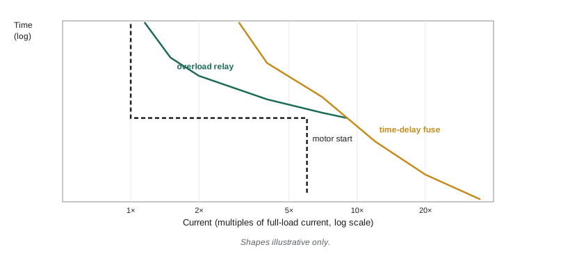
A motor circuit has two kinds of protection, and master exams test whether you can keep them apart. Short-circuit and ground fault protection, the Code's 200-series overcurrent protection, has to open fast when a fault draws hundreds or thousands of amperes, but it must let the motor start, which can draw six or more times running current for several seconds. Overload protection has to do the opposite: ignore the brief starting surge, but trip on a moderate overcurrent that lasts long enough to cook the windings, such as a jammed auger, a dragging bearing or a lost phase. No single device does both jobs well on most motors, which is why a typical starter has fuses or a breaker ahead of it and an overload relay inside it.
This lesson goes through both kinds of protection in the depth exams expect: the protection table and its device types, the provisions for the next larger size and for motors that will not start, feeder protection for several motors, overload protection and the service factor rule, thermal protectors built into motors, single-phasing, undervoltage protection and automatic restart. The example is the replacement of a failed grain-dryer motor at Hartley Farms, where the farm's old protection settings turned out to be wrong in two different ways. Table values used here are illustrative; look up the real values in your own 2024 CE Code.
Why starting current drives the short-circuit device
When a squirrel-cage motor starts across the line, it draws its locked-rotor current until the rotor comes up to speed. Locked-rotor current is commonly five to eight times full-load current, and on a heavily loaded fan or auger the acceleration can take several seconds. A fuse or breaker sized at 125% of full-load current, like the conductors, would open on every start. So the Code allows the short-circuit and ground fault device to be rated well above the conductor ampacity, and relies on the overload relay to protect the conductors and motor from running overload. The conductors are still protected against short circuits, because fault currents are far higher than starting currents and open the device quickly.
The protection table and device types
The Code's motor protection table gives the maximum rating or setting of the short-circuit and ground fault device as a multiple of the table full-load current, with separate columns for each device type: non-time-delay fuses, time-delay fuses, inverse-time circuit breakers and instantaneous-trip breakers. The table also distinguishes motor types and starting methods, because a motor that starts with reduced voltage draws less starting current. On an exam, the steps are always the same: find the table full-load current, identify the device type and motor type, read the multiplier from the protection table, multiply, and then apply the rule's provisions for standard ratings.
| Device type (illustrative multipliers only) | Illustrative maximum | Why it differs |
|---|---|---|
| Non-time-delay fuse | 300% of FLC | Opens quickly; needs a large margin to ride through starting |
| Time-delay fuse | 175% of FLC | Built to tolerate inrush, so it can be rated closer to running current |
| Inverse-time breaker | 250% of FLC | Thermal-magnetic trip tolerates some starting current |
| Instantaneous-trip breaker | 800% to 1300% of FLC | Magnetic only; must be part of a listed combination with overload protection |
Instantaneous-trip breakers deserve a special note. Because they have no thermal element, they can only be used as part of a combination starter that has been tested and approved with a specific overload relay, and they are adjusted rather than chosen from standard ratings. Exam questions about them usually test whether you know they are allowed only in that combination.
Worked problem
Protecting the replacement dryer motor (illustrative values)
The new 30 hp, 600 V three-phase dryer fan has an illustrative table full-load current of 32 A. It will be protected by time-delay fuses. Using the illustrative 175% from the table above, find the maximum fuse rating.
Show solution
- Maximum = 1.75 × 32 = 56 A (illustrative multiplier).
- Standard fuse ratings near 56 A are 50 A and 60 A. The rule's provision for the next larger size decides whether 60 A is permitted.
- If the motor still cannot start on the chosen fuse, a second provision allows a larger fuse up to a stated ceiling.
Answer: 56 A maximum before the standard-size provisions, with illustrative values.
The next larger size and motors that will not start
A calculated maximum rarely lands on a standard fuse or breaker rating. The Code has a provision allowing the next higher standard rating when the calculated value does not correspond to one, within limits. A second provision covers the case where the motor will not start on the device selected under the normal maximum: the rating may then be increased further, but not beyond a stated higher multiple of full-load current that depends on the device type. These provisions are a favourite exam trap, because a candidate who rounds down always loses the mark, and a candidate who jumps straight to the higher ceiling without noting that the motor failed to start also loses it. Write both provisions on your lookup sheet in your own words, with the rule number.
At Hartley Farms, the old fan had been protected by 30 A non-time-delay fuses, far below what the rules allow, and the fuses blew on cold mornings when the fan started against stiff, damp grain. The farm's handyman had responded by putting in 100 A fuses, far above what the rules allow. Priya replaces them with time-delay fuses sized from the table, and the fan starts reliably while the circuit is properly protected.
Feeder protection for several motors
A feeder supplying several motors needs its own short-circuit and ground fault protection. The rule bases the maximum feeder device rating on the largest motor's maximum branch-circuit device rating, plus the full-load currents of all the other motors on the feeder. The reasoning is that the largest motor might start while all the others are already running; the feeder device must carry that combination without opening. Where two or more motors have the same largest device rating, only one of them is treated as the largest. If the result does not land on a standard rating, the feeder device is the next standard rating below, not above, unless your Code says otherwise; check this carefully, because it is the opposite of the branch-circuit provision.
Worked problem
Feeder protection for the motor control centre (illustrative values)
The motor control centre supplies the 30 hp fan (32 A, maximum branch fuse 56 A from the example above), two 10 hp augers (11 A each) and a 5 hp elevator (6.1 A). Find the maximum feeder fuse rating.
Show solution
- Largest motor's maximum branch device: 56 A.
- Other motors' full-load currents: 11 + 11 + 6.1 = 28.1 A.
- Maximum feeder device: 56 + 28.1 = 84.1 A; choose a standard rating as the rule directs.
Answer: About 84 A maximum with illustrative values.
Overload protection and the service factor
Overload protection protects the motor and its branch circuit conductors from running overload. Rule 28-306 sets the maximum trip setting of an overload relay as a multiple of the motor's nameplate full-load current, not the table value: 125% for motors marked with a service factor of 1.15 or more or with a temperature rise of 40 °C or less, and 115% for other motors. The service factor is a manufacturer's statement that the motor can carry a modest continuous overload without damage; a 1.15 service factor means 15% overload is tolerable. If the motor cannot start or carry its load at the normal setting, the rule allows a somewhat higher setting within stated limits.
Overload relays come in several kinds. Bimetallic thermal relays heat a strip with the motor current and trip when it bends far enough. Eutectic alloy relays use a solder pot that melts and releases a ratchet. Electronic overload relays measure current directly and model the motor's heating; they can also detect phase loss, phase unbalance and ground faults. The heater elements in thermal relays are chosen from the manufacturer's selection table using the nameplate current and sometimes the ambient temperature difference between motor and starter. The Code does not give that table; the manufacturer does.
Worked problem
Setting the replacement fan's overload
The replacement fan's nameplate shows 31.2 A full-load current and a service factor of 1.15. What is the maximum overload setting?
Show solution
- Service factor 1.15, so 125% applies.
- Maximum = 1.25 × 31.2 = 39 A, using the nameplate current.
Answer: 39 A.
The old fan's overload relay had been set at its maximum dial position years ago and never touched. With the new motor's lower nameplate current, the old setting would have allowed nearly 50% overload. Priya sets the electronic relay to the new nameplate value and records the setting on the starter door, which the farm's insurer later asks to see.
Thermal protectors and other protective devices
Many small motors, especially fractional-horsepower single-phase motors on fans, pumps and compressors, have thermal protectors built into the windings. These open the motor circuit when the windings overheat and may reset automatically or manually. The Code accepts a thermal protector as the motor's overload protection if it is part of the approved motor and meets the conditions in the rules. Where the protector resets automatically, the rules about automatic restart, covered below, matter: a protector that resets by itself must not create a hazard by restarting machinery unexpectedly.
Some motors also have devices that are not overload protection in the Code's sense: motor winding temperature sensors that feed a relay, vibration monitors and bearing temperature sensors. These are good practice on large motors and are common at plants Marcus has worked at, but they supplement rather than replace the required overload protection unless approved for that purpose.
Single-phasing
If one phase of a three-phase supply is lost, a running three-phase motor keeps turning but draws much higher current on the remaining two phases, and the windings overheat quickly. This is called single-phasing, and it is a common cause of motor failure on rural lines where a single fuse on the utility's pole can blow in a storm. Overload relays in all three phases, which the rules generally require for three-phase motors, will usually detect it; electronic relays detect it faster and more reliably. Phase-loss relays are a further option. On exams, the question is usually why the Code requires overload elements in each phase, and the answer is single-phasing.
Worked problem
Why the fan burned out
The failed dryer motor's windings showed the classic burn pattern of single-phasing, and the old starter had overload heaters in only two of the three phases. What happened, and what does the new installation do differently?
Show solution
- A lost phase put the motor's current into two windings, with higher current in one phase than the other.
- With only two heaters, the relay could miss an overload in the phase without a heater.
- The new electronic relay measures all three phases and trips on phase loss and unbalance.
Answer: The old relay could not see the overloaded phase; the new one monitors all three.
Undervoltage protection and automatic restart
If the supply voltage drops or fails and then returns, a motor that restarts automatically can injure someone who has started clearing a jam or working on the driven machinery in the meantime. The 28-400 series rules require undervoltage protection, often called low-voltage protection, where automatic restart would create a hazard. A magnetic starter with a three-wire control circuit and momentary start button provides it: when the voltage drops, the contactor drops out and stays out until someone presses start again. A two-wire control circuit, such as a float switch or thermostat, restarts the motor automatically when power returns and is used only where automatic restart is safe, such as a sump pump.
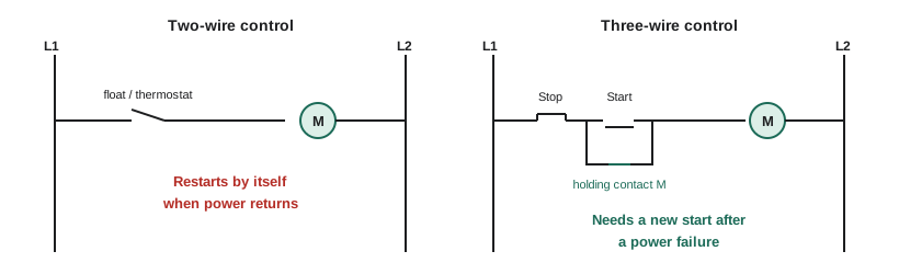
At Hartley Farms, the augers use three-wire control so that a power blip cannot restart them while someone is in the bin, and the farm's lockout procedure adds a padlock on the disconnect before anyone enters. The aeration fans use two-wire control from a grain-moisture controller, because they are guarded and restarting them is not a hazard. Priya writes both decisions into the job file.
A protection worksheet
# Motor protection summary (multipliers are illustrative; read yours from the Code).
table_flc = 32.0        # from the motor table (illustrative)
nameplate_flc = 31.2    # from the motor nameplate
service_factor = 1.15
device_pct = {'non-time-delay fuse': 3.00, 'time-delay fuse': 1.75, 'inverse-time breaker': 2.50}

for device, pct in device_pct.items():
    print(f'{device:22s} max {pct * table_flc:6.1f} A')
ol = 1.25 if service_factor >= 1.15 else 1.15
print('overload setting max', round(ol * nameplate_flc, 2), 'A')
others = [11, 11, 6.1]
print('feeder device max', round(1.75 * table_flc + sum(others), 1), 'A (time-delay fuses)')non-time-delay fuse max 96.0 A time-delay fuse max 56.0 A inverse-time breaker max 80.0 A overload setting max 39.0 A feeder device max 84.1 A (time-delay fuses)
Common mistakes
MistakeUsing the table full-load current to set the overload relay.
InsteadOverloads use the motor's nameplate full-load current.
MistakeRounding the branch device down when the calculated maximum is between standard ratings.
InsteadCheck the next-larger-size provision; it usually allows the next standard rating up.
MistakeApplying the higher not-starting ceiling straight away.
InsteadThat provision applies only when the motor will not start on the normal maximum.
MistakeUsing an instantaneous-trip breaker on its own.
InsteadIt is permitted only as part of an approved combination with overload protection.
MistakeUsing two-wire control where an automatic restart could injure someone.
InsteadUse three-wire control or another form of undervoltage protection where restart is hazardous.
Summary and key terms
- The short-circuit device must let the motor start; the overload relay protects against running overload.
- Short-circuit device maximums come from the protection table by device type, based on table full-load current.
- Provisions allow the next standard size and a higher rating if the motor will not start, within limits.
- Feeder device: the largest motor's maximum device plus the other motors' full-load currents.
- Overloads: up to 125% or 115% of nameplate current under Rule 28-306; three-phase motors need protection against single-phasing; hazardous restarts need undervoltage protection.
- Locked-rotor current
- The current a motor draws at standstill when first energized.
- Service factor
- A marked multiplier indicating the continuous overload a motor can tolerate.
- Single-phasing
- Loss of one phase of a three-phase supply to a running motor.
- Thermal protector
- A device built into a motor that opens on winding overheating.
- Three-wire control
- A control circuit with momentary start and stop buttons and a holding contact.
Practice problems
Work each problem on paper first, then reveal the answer to check.
Table FLC 20 A, inverse-time breaker, illustrative 250%: maximum breaker?
Show answer
50 A before the standard-size provisions.
Nameplate 18 A, service factor 1.0, no marked temperature rise: maximum overload?
Show answer
1.15 × 18 = 20.7 A.
Largest motor's maximum device 70 A; others' FLC 15 and 9 A: maximum feeder device?
Show answer
94 A, then apply the rule's standard-rating direction.
Which control circuit provides undervoltage protection?
Show answer
Three-wire control with a holding contact.
Lesson quiz · 5 questions
Score 60% or more to complete this lesson.
Create a free account to save your progress, take quizzes and earn a certificate.