
MELC-105 · Lesson 4 of 12 · 23 min
Capacitors and power factor correction
▶ Video coming soon A video version of this lesson is on the way.
Power factor correction rarely comes up on a residential job, which is why capacitor questions catch so many candidates on master exams. Section 26's capacitor rules are short, and the arithmetic behind power factor correction is a direct extension of the power triangle from MELC-102. An hour with this lesson turns a scary-looking question into a sure mark. The questions usually ask one of four things: how many kilovars of capacitance are needed to raise the power factor to a target, what the conductor ampacity to a capacitor must be, how a capacitor is discharged and disconnected, or where a capacitor can be connected to a motor circuit and how that affects the overload setting.
The example is Hartley Farms again. After the grain dryer expansion, the farm's utility bill showed a power factor penalty: the utility charges commercial and farm customers extra when their average power factor falls below a threshold in the rate schedule, because low power factor means the utility has to supply more current for the same real power. Gord asks Priya to size a capacitor bank. As always, no Code text or tables are reproduced; rules are explained in plain words and any value from a table is illustrative. Check your own 2024 CE Code.
Why power factor matters
An induction motor needs magnetizing current to set up its magnetic field, and that current is reactive: it flows back and forth between the supply and the motor each cycle without doing work. The real power, in kilowatts, does the work; the reactive power, in kilovars, magnetizes the motor; and the apparent power, in kilovolt-amperes, is what the conductors, transformers and the utility's equipment have to carry. Power factor is the ratio of real to apparent power. A lightly loaded motor has a poor power factor, often 0.5 to 0.7, because its magnetizing current stays roughly the same while its real power drops.
Low power factor costs money in three ways. The utility may charge a penalty or bill on kVA demand rather than kW. The higher current increases losses in the customer's own feeders, which shows up as heat and voltage drop. And transformers and feeders reach their ampacity limits sooner, so a plant with poor power factor may need a larger service than one with good power factor. Capacitors supply reactive power locally, so the supply no longer has to carry it, which raises the power factor seen by the utility.
Sizing a capacitor bank
The calculation uses the power triangle. With real power P and an existing power factor angle θ1, the existing reactive power is P × tan θ1. For a target power factor angle θ2, the reactive power after correction is P × tan θ2. The capacitor must supply the difference. Power factor angles come from the inverse cosine of the power factor, so the whole calculation is three steps on a calculator.
Worked problem
Correcting the dryer motor control centre
The motor control centre at Hartley Farms draws 120 kW at a power factor of 0.72 during drying season. Find the capacitor kilovars needed to raise the power factor to 0.95.
Show solution
- θ1 = cos⁻¹(0.72) = 43.95°; tan θ1 = 0.9639.
- θ2 = cos⁻¹(0.95) = 18.19°; tan θ2 = 0.3287.
- Q_C = 120 × (0.9639 − 0.3287) = 120 × 0.6352 = 76.2 kvar.
Answer: About 76 kvar; Priya would choose a standard bank size of 75 kvar and check the resulting power factor.
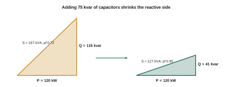
Rounding down to a standard size leaves the power factor slightly below target; rounding up raises it slightly above. Utilities set penalty thresholds, often around 0.9, and overcorrecting toward a leading power factor brings its own problems, so most designers aim for 0.95 and accept a close standard size. With 75 kvar, the remaining reactive power is 120 × 0.9639 − 75 = 40.7 kvar, giving a power factor of 120 / √(120² + 40.7²) = 0.947.
Worked problem
Current before and after (600 V three-phase)
Using the motor control centre above, find the line current before and after correction with a 75 kvar bank.
Show solution
- Before: S = 120 / 0.72 = 166.7 kVA; I = 166 700 / (1.732 × 600) = 160.4 A.
- After: S = √(120² + 40.7²) = 126.7 kVA; I = 126 700 / (1.732 × 600) = 121.9 A.
Answer: The feeder current drops from about 160 A to about 122 A for the same real power.
Where to connect the capacitors
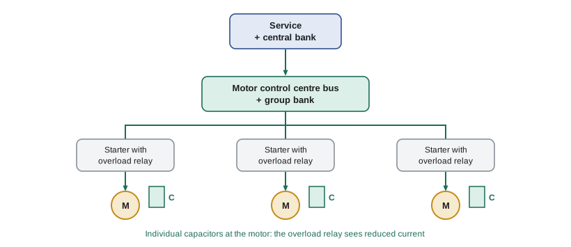
Capacitors can be installed at three levels. Individual correction puts a capacitor at each large motor, switched with the motor so that the capacitor is only connected when the motor runs. Group correction puts a bank at a motor control centre or distribution panel, serving several motors. Central correction puts an automatically switched bank at the service, with steps that switch in and out as the load changes. Individual correction reduces current in the motor branch circuit as well as upstream; central correction is cheaper per kilovar and adjusts to changing loads but does nothing for the branch circuits.
When a capacitor is connected on the load side of a motor's overload relay, the relay sees the reduced current, not the motor's actual current. The rules address this: the overload relay must be selected or set based on the reduced current that actually flows through it, not the motor nameplate current, so the motor still gets proper protection. On an exam, a question that mentions a capacitor connected at the motor terminals is often really a question about overload settings. The capacitor must also not be so large that it overcorrects the motor at no load, which can cause self-excitation when the motor is switched off: the coasting motor and capacitor can generate a high voltage. Motor manufacturers publish maximum capacitor sizes for this reason.
Conductors and protection for capacitors
Capacitor current is easy to calculate from the kilovar rating and voltage, but the rules require the conductors to a capacitor to have an ampacity above its rated current. The reasons are that capacitors are manufactured with a tolerance that allows slightly more capacitance than marked, that the supply voltage may run above nominal, and that harmonic currents from drives and other non-linear loads flow preferentially into capacitors. Look up the multiplier in your Code; the example below uses an illustrative 135% purely to show the method.
Worked problem
Conductors to the 75 kvar bank (illustrative multiplier)
The 75 kvar bank is three-phase at 600 V. Find its rated current, and the minimum conductor ampacity with an illustrative multiplier of 135%.
Show solution
- Rated current = 75 000 / (1.732 × 600) = 72.2 A.
- Minimum ampacity = 1.35 × 72.2 = 97.4 A (illustrative multiplier).
Answer: Rated current 72.2 A; about 97 A of conductor ampacity with the illustrative multiplier.
The capacitor circuit also needs overcurrent protection and a disconnecting means, unless the capacitor is connected on the load side of a motor controller and switched with the motor, in which case the motor circuit's devices may serve. The disconnect must open all ungrounded conductors and have a rating above the capacitor current, for the same reasons. These details are a quick lookup: Priya has the capacitor rules on one line of her sheet, with the conductor multiplier and the disconnect requirement.
Discharge and safety
A capacitor stores energy, and a disconnected capacitor can stay charged at a dangerous voltage. The rules require capacitors to have a means of discharging the stored energy automatically when disconnected, within a stated time and to a stated safe voltage, usually by discharge resistors built into the capacitor or a motor winding connected directly across it. Workers are also expected to verify the absence of voltage and to short and ground capacitor terminals before touching them, which is part of the safe work practices in CSA Z462. Capacitor enclosures must be guarded and bonded, and liquid-filled capacitors above a certain size have location rules similar to liquid-filled transformers.
Marcus tells the study group about a shutdown where a maintenance worker opened a capacitor cabinet that had been disconnected for less than a minute. The discharge resistors had failed open. The worker's insulated tester showed voltage, and nobody was hurt, but the story makes the point better than any rule: always test before touch, and do not trust discharge resistors without verification.
Harmonics and resonance
Variable-frequency drives, LED drivers and other electronic loads draw non-sinusoidal current containing harmonics. A capacitor bank and the supply transformer's inductance form a resonant circuit, and if the resonant frequency lands near a harmonic present in the system, harmonic currents and voltages can be amplified, blowing capacitor fuses or damaging the capacitors and other equipment. The usual solution is a detuned bank, where each capacitor step has a series reactor that moves the resonant frequency below the dominant harmonics. The Code does not cover harmonic design in detail, but exams may ask why capacitor fuses keep blowing at a plant full of drives, and the answer is resonance with harmonics.
At Hartley Farms, the new dryer fan runs on a drive. Priya's supplier recommends a detuned bank for the motor control centre, and the extra cost is small compared with the risk of resonance. She records the recommendation, the bank's tuning frequency from the supplier's data, and the decision in the job file.
A capacitor sizing tool
import math

def kvar_needed(kw, pf_now, pf_target):
    t1 = math.tan(math.acos(pf_now))
    t2 = math.tan(math.acos(pf_target))
    return kw * (t1 - t2)

def pf_after(kw, pf_now, kvar_bank):
    q = kw * math.tan(math.acos(pf_now)) - kvar_bank
    return kw / math.hypot(kw, q)

kw, pf0 = 120, 0.72
need = kvar_needed(kw, pf0, 0.95)
print('kvar needed for 0.95:', round(need, 1))
for bank in (60, 75, 90):
    print(f'{bank} kvar bank -> pf {pf_after(kw, pf0, bank):.3f}')
print('bank current at 600 V:', round(75000 / (math.sqrt(3) * 600), 1), 'A')kvar needed for 0.95: 76.2 60 kvar bank -> pf 0.907 75 kvar bank -> pf 0.947 90 kvar bank -> pf 0.978 bank current at 600 V: 72.2 A
Try different banks to see how the power factor moves; the 90 kvar bank pushes the power factor close to unity, which most designers avoid at light load because the bank can then overcorrect.
Reading the utility bill
Before sizing anything, Priya reads the farm's bill with Gord. The utility's rate for the farm measures both kilowatt-hours and peak demand, and its rate schedule applies a demand adjustment when the average power factor in the billing period falls below a stated threshold. The bill shows the measured kW demand, the kVA demand and the calculated power factor. In the drying months, the power factor dropped into the low 0.7s, and the adjustment added a noticeable amount to each bill. Outside drying season, with the dryer fans off, the power factor was above the threshold and there was no adjustment. That pattern tells Priya that the problem is the motors at the motor control centre, not the house or the shop, which is why she sizes group correction for the motor control centre rather than a central bank at the service.
Rate schedules differ between utilities and provinces, and the Code does not deal with billing at all. On an exam, the utility's threshold is usually given in the question. The calculation is the same: find the kvar needed to reach the threshold or a stated target, choose a standard size, and check the resulting power factor. Some questions run the other way, giving a capacitor bank and asking for the new power factor or the new current, which uses the same triangle.
A worked exam set
Denise gives the study group three capacitor questions in a row, each a slightly different pattern. In the first, a plant draws 250 kVA at 0.8 power factor and wants 0.95; the group must notice that the real power is 250 × 0.8 = 200 kW before applying the tangent formula, giving about 84 kvar. In the second, a 40 hp motor with a known power factor and efficiency has a capacitor at its terminals, and the question asks what the overload relay should be set from; the answer is the reduced current through the relay, not the nameplate. In the third, a 100 kvar bank at 600 V needs conductors, and the group calculates the rated current, 96.2 A, and then applies the Code's multiplier from their own books.
Tyler gets the first one wrong by using 250 kVA in place of real power, a mistake Denise says she saw on real exams more than any other capacitor error. The power triangle has three sides and the formula needs the real power side; if a question gives kVA, multiply by the power factor first. Priya adds that line to her lookup sheet in red.
Common mistakes
MistakeCalculating capacitor kvar from the difference of power factors instead of tangents.
InsteadUse P × (tan θ1 − tan θ2).
MistakeLeaving the overload setting at the motor nameplate value when a capacitor is on the load side of the relay.
InsteadSet the relay for the reduced current that flows through it.
MistakeSizing capacitor conductors at the rated current.
InsteadUse the Code's multiplier above rated current.
MistakeTrusting discharge resistors without testing.
InsteadVerify absence of voltage before touching capacitor terminals.
MistakeIgnoring harmonics at a plant full of drives.
InsteadCheck for resonance; consider a detuned bank.
Summary and key terms
- Low power factor raises current, losses and utility charges; capacitors supply reactive power locally.
- Capacitor kvar = P × (tan θ1 − tan θ2); choose a close standard size and check the result.
- Individual capacitors at motors reduce current through the overload relay, which must then be set for the reduced current.
- Capacitor conductors and disconnects are rated above the capacitor's rated current; capacitors need automatic discharge.
- Harmonics can cause resonance with capacitor banks; detuned banks avoid it.
- Power factor
- The ratio of real power to apparent power.
- Reactive power
- Power that oscillates between source and load to set up magnetic and electric fields, in kvar.
- Capacitor bank
- A group of capacitors installed together, often in switched steps.
- Detuned bank
- A capacitor bank with series reactors that shift its resonant frequency away from system harmonics.
- Self-excitation
- Voltage generated by a coasting induction motor with a capacitor connected across it.
Practice problems
Work each problem on paper first, then reveal the answer to check.
100 kW at 0.8 pf: kvar to reach 0.95?
Show answer
100 × (0.75 − 0.3287) = 42.1 kvar.
50 kvar at 600 V three-phase: rated current?
Show answer
48.1 A.
Why must a capacitor at the motor terminals change the overload setting?
Show answer
The relay sees reduced current, so it must be set for that current.
Why do capacitor fuses blow at a plant with many drives?
Show answer
Harmonic resonance can amplify currents into the capacitors.
Lesson quiz · 5 questions
Score 60% or more to complete this lesson.
Create a free account to save your progress, take quizzes and earn a certificate.