
MELC-104 · Lesson 9 of 12 · 23 min
Separately derived systems
▶ Video coming soon A video version of this lesson is on the way.
A separately derived system is a new electrical system created inside a building from a source that has no direct electrical connection between its output conductors and the conductors of the system that feeds it. The everyday example is a dry-type transformer that steps 600 V down to 208Y/120 V for receptacles and lighting. The transformer's secondary winding is magnetically coupled to its primary, but no conductor connects the two. As far as grounding is concerned, the secondary is a brand-new system, and it needs everything a new system needs: a system bonding jumper, a grounding conductor and a connection to an electrode.
Generators, some uninterruptible power supplies, and some solar and battery inverters can also be separately derived systems, depending on how their neutrals are connected. Getting the grounding of these systems wrong is one of the most common sources of objectionable current, nuisance tripping and real hazards in commercial buildings, and it is a reliable source of exam questions. This lesson covers the rule on separately derived systems, the choices it allows, and the generator question that confuses so many people.
Requirements are paraphrased. Read the rule on separately derived solidly grounded systems, Rule 10-212, and the related Appendix B figures in your own 2024 CE Code Part I.
The clinic's transformer
The Gaetz Avenue dental clinic is supplied at 347/600 V, like the rest of the strip mall, and needs 208Y/120 V for its dental chairs, compressors, X-ray equipment and receptacles. Parkland Valley is installing a 75 kVA dry-type transformer in the clinic's electrical room. From MELC-102, the group already knows its currents: about 72.2 A on the 600 V primary and about 208.2 A on the 208 V secondary. Now the question is how to ground and bond it.
Tyler asks why the transformer cannot simply use the building's existing grounding. Marcus explains that the 600 V system's neutral is grounded at the service, but the new 208Y/120 V system has a neutral of its own, at the transformer's secondary star point, which has no connection to the service neutral. Unless something connects that new neutral to the bonding system and to ground, the secondary is effectively an ungrounded system, and a fault to a bonded enclosure on the 120 V side would have no path back to its source.
What makes a system separately derived
The test is the absence of a direct electrical connection between the conductors of the two systems, including the neutral. A conventional two-winding transformer is the clearest case: no conductor joins its primary and secondary. An autotransformer, by contrast, shares a winding between input and output, so its output is directly connected to its input and it is not separately derived.
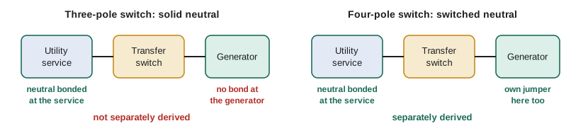
For generators, the answer depends on the transfer switch. If the transfer switch switches the neutral along with the phase conductors, so that the generator's neutral is disconnected from the utility neutral when the generator is running, the generator is a separately derived system and needs its own system bonding jumper. If the transfer switch leaves the neutral solidly connected through, so that the generator shares the utility system's neutral, the generator is not separately derived, and it must not have its own system bonding jumper, because that would create a second neutral-to-bonding connection.
| Source | Neutral connection to the supply system | Separately derived? | Own system bonding jumper? |
|---|---|---|---|
| Two-winding dry-type transformer | None | Yes | Yes |
| Autotransformer | Shared winding | No | No |
| Generator with switched-neutral transfer switch | Disconnected when on generator | Yes | Yes |
| Generator with solid-neutral transfer switch | Solidly connected through | No | No (bond only at the service) |
| Inverter system | Depends on its design and connection | Check the manufacturer and Section 64 | Depends |
The system bonding jumper
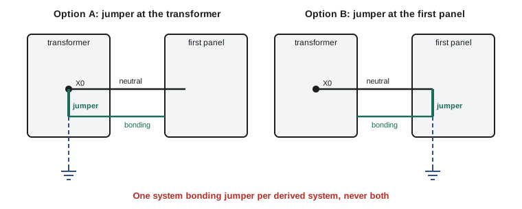
A separately derived solidly grounded system needs a system bonding jumper that connects its grounded conductor, usually the secondary neutral, to the bonding system. Subrule 10-212(1) allows that connection to be made at the source, such as in the transformer enclosure, or at the first disconnecting means or overcurrent device on the secondary side, or at another point the rule permits, but at only one of them. The single-point rule applies to a derived system exactly as it applies at the service: one connection between the neutral and the bonding system per system.
The choice of location has practical consequences. If the jumper is in the transformer, the secondary conductors to the first panel must include a neutral and a bonding conductor kept separate, and the panel's neutral bar is isolated. If the jumper is at the first panel, the panel's neutral is bonded there, and the transformer enclosure is bonded through the secondary bonding conductor. Either works if done consistently; mixing the two, with jumpers at both, is the error.
The size of a field-installed system bonding jumper comes from Table 16, entered with the quantity the rule specifies, usually the ampacity of the largest ungrounded conductor of the derived system. A transformer supplied with a factory-installed jumper sized for its rating avoids the calculation.
Worked problem
Sizing the clinic transformer's jumper
The clinic transformer's secondary conductors have an ampacity of 230 A. The jumper will be field-installed at the first panel. Using practice table P-16 from lesson 6, find its size code.
Show solution
- Enter Table 16 with the ampacity of the largest ungrounded secondary conductor: 230 A.
- 230 A falls in the practice band 201 to 300 A.
- Practice size: B6 copper. On the exam, use the real Table 16 and the rule's stated entry quantity.
Answer: Practice size B6 (copper).
Grounding the derived system
A separately derived system also needs its grounded conductor connected to ground through a grounding conductor, from the point where the system bonding jumper is located to a suitable grounding electrode. The rule describes which electrodes may be used, often the nearest effective one such as bonded building steel, metal water piping that qualifies, or the building's main electrode system. The grounding conductor is sized from Table 17 using the derived system's largest conductors, as lesson 5 described.
Subrule 10-212(2) adds an important alternative for derived systems operating at 750 V or less: the system may be grounded through the bonding conductor of its primary supply, back to the service where the main grounding connection is made. That is how many commercial transformers are grounded in practice, avoiding a long separate grounding conductor to a distant electrode. The rule sets the conditions, including the size of that primary bonding conductor; read them carefully, because exam questions test exactly when the option is available.
Worked problem
The clinic transformer's grounding
The clinic transformer is a 600 to 208Y/120 V unit, well under 750 V, fed by a primary feeder with its own bonding conductor back to the service. The building steel near the electrical room is bonded. What grounding options does the electrician have, in general terms?
Show solution
- Option 1: run a grounding conductor, sized from Table 17 for the secondary conductors, from the system bonding jumper location to the bonded building steel or another suitable electrode nearby.
- Option 2: because the system is 750 V or less, ground it through the primary supply's bonding conductor, under the conditions of 10-212(2), which may require that conductor to meet a minimum size.
- Either way, there is exactly one system bonding jumper, at the transformer or at the first panel.
Answer: A nearby electrode via its own grounding conductor, or the primary bonding conductor under 10-212(2).
Currents in the clinic transformer
Exam questions on separately derived systems often combine grounding with the transformer calculations from MELC-102. The currents set the sizes of the secondary conductors and their overcurrent protection, and the secondary conductor ampacity then sets the jumper and grounding conductor sizes.
Worked problem
Primary and secondary currents
Find the rated primary and secondary line currents of the 75 kVA, 600 V to 208Y/120 V three-phase transformer.
Show solution
- Primary: 75 000 / (1.732 × 600) ≈ 72.2 A.
- Secondary: 75 000 / (1.732 × 208) ≈ 208.2 A.
- The secondary conductors, chosen with the Section 4 tables and the Rule 26-256 requirements covered in MELC-102, have an ampacity of at least that, and the grounding and bonding sizes follow from them.
Answer: About 72.2 A primary and 208.2 A secondary.
import math

def three_phase_current(kva, v_ll):
    return kva * 1000 / (math.sqrt(3) * v_ll)

for kva in (30, 45, 75, 112.5, 150):
    pri = three_phase_current(kva, 600)
    sec = three_phase_current(kva, 208)
print(f'{kva:6.1f} kVA: primary {pri:6.1f} A, secondary {sec:6.1f} A')30.0 kVA: primary 28.9 A, secondary 83.3 A 45.0 kVA: primary 43.3 A, secondary 124.9 A 75.0 kVA: primary 72.2 A, secondary 208.2 A 112.5 kVA: primary 108.3 A, secondary 312.3 A 150.0 kVA: primary 144.3 A, secondary 416.4 A
Edit the list to include the transformer sizes on your own jobs. The secondary current is the starting point for every grounding and bonding size on the derived system.
The generator question
Hartley Farms has a 60 kW standby generator for the grain dryers, connected through a transfer switch at the farm's main service. Marcus asks the question that catches many electricians: does the generator need its own neutral-to-frame bond?
The answer depends entirely on the transfer switch. Denise walks the group through both cases. If the transfer switch is a three-pole unit that switches only the phase conductors, the generator neutral stays connected to the utility neutral at all times, and the neutral is bonded at the service. The generator is not separately derived. Its frame is bonded through the bonding conductor in the feeder, and its neutral must not be bonded to its frame, or normal neutral current will split between the neutral and the bonding path, as lesson 11 shows.
If the transfer switch is a four-pole unit that also switches the neutral, the generator neutral is disconnected from the utility neutral when the generator runs. The generator is then a separately derived system and needs its own system bonding jumper, normally at the generator or its first disconnect, and its own grounding arrangement under 10-212. Many portable and standby generators are shipped with the neutral bonded to the frame; the installer has to check, and remove or keep that bond according to the transfer switch.
Inverters and storage
Solar and battery inverters add another layer. Some inverters are designed to be separately derived when operating in backup mode, others never are, and many depend on a specific connection described in the manufacturer's instructions. Section 64 adds requirements for renewable energy and storage systems, and the 2024 edition expanded them. For an exam, the principle to hold on to is the same one that governs transformers and generators: each system has exactly one neutral-to-bonding connection, and whether a source needs one of its own depends on whether its neutral is separate from the supply system's neutral.
A field story
Denise ends the lesson with a call from her inspection years. A new office building had nuisance tripping on its ground fault protection every afternoon. The electrical contractor had installed several 600 to 208Y/120 V transformers, each with a system bonding jumper in the transformer and another at the first panel. Every afternoon, as the air conditioning loads rose, neutral current on the 208 V systems divided between the neutrals and the bonding paths, some of it finding its way back through the building steel and the 600 V bonding system, where the main service's ground fault relay saw it as a fault. Removing the extra jumpers fixed it. The rule was not a technicality; it was the reason the building could not stay energized.
Common mistakes
MistakeTreating a transformer secondary as already grounded by the building's service.
InsteadA separately derived system needs its own system bonding jumper and grounding.
MistakeInstalling system bonding jumpers at both the transformer and the first panel.
InsteadInstall one jumper per system, at one permitted location.
MistakeBonding a generator neutral to its frame when the transfer switch has a solid neutral.
InsteadA solid-neutral arrangement is not separately derived; bond only at the service.
MistakeSizing the derived system's grounding conductor from the primary conductors.
InsteadUse the derived system's secondary conductors with Table 17.
MistakeAssuming the primary bonding conductor can always serve as the grounding path.
InsteadThat option under 10-212(2) applies to systems of 750 V or less, with conditions.
Summary and key terms
- A separately derived system has no direct electrical connection, including the neutral, to the system that supplies it.
- It needs one system bonding jumper, at the source or first disconnecting means, sized from Table 16.
- It needs a grounding conductor to a suitable electrode, sized from Table 17 with the derived system's conductors, or, at 750 V or less, may use the primary bonding conductor under 10-212(2).
- A generator is separately derived only if the transfer switch switches the neutral.
- Extra neutral-to-bonding connections cause objectionable current and nuisance ground fault trips.
- Separately derived system
- A system supplied by a source with no direct electrical connection to the conductors of another system.
- Autotransformer
- A transformer with a shared winding, whose output is directly connected to its input.
- Switched-neutral transfer switch
- A transfer switch that also disconnects the neutral, making a generator separately derived.
- System bonding jumper
- The single connection between a system's grounded conductor and its bonding system.
- Primary bonding conductor option
- Grounding a derived system of 750 V or less through the bonding conductor of its supply, under the stated conditions.
Practice problems
Work each problem on paper first, then reveal the answer to check.
Is a 600 to 208Y/120 V two-winding transformer separately derived?
Show answer
Yes; no conductor connects primary and secondary.
Find the secondary current of a 45 kVA, 208 V three-phase transformer.
Show answer
45 000 / (1.732 × 208) ≈ 124.9 A.
A generator connects through a three-pole transfer switch. Where is its neutral bonded?
Show answer
Only at the service; not at the generator.
How many system bonding jumpers does each separately derived system have?
Show answer
One.
Lesson quiz · 5 questions
Score 60% or more to complete this lesson.
Create a free account to save your progress, take quizzes and earn a certificate.