
MELC-104 · Lesson 6 of 12 · 25 min
Bonding conductors and bonding jumpers
▶ Video coming soon A video version of this lesson is on the way.
If grounding conductors are the system's connection to earth, bonding conductors are its connection to safety. Every branch circuit and feeder in a building needs a continuous, low-impedance bonding path from the metal it serves back to the source, so that a fault becomes a short circuit and the overcurrent device opens. Sometimes that path is a separate conductor in a cable or raceway. Sometimes it is the raceway or cable armour itself. And at certain points, such as the service, a transformer or a concentric knockout, it is completed by a short conductor called a bonding jumper.
This lesson covers the sizing of bonding conductors with Table 16, the different kinds of bonding jumper, and what happens when circuits are run in parallel. Bonding conductor sizing is the most frequently examined lookup in Section 10, so the lesson spends time on the method and the traps.
The Table 16 values are not reproduced here. As in lesson 5, the examples use an invented practice table with made-up size codes; use the real table in your own 2024 CE Code Part I on the exam.
The feeder to the shop
At Hartley Farms, Parkland Valley is installing a new 100 A feeder from the farm's main service to the grain-drying shop. Tyler is pulling the conductors and asks Priya why the bare bonding conductor in the cable is so much smaller than the phase conductors. If it has to carry a fault, he says, surely it should be as big as the conductors that carry the load.
Priya explains it the way Denise explained it to her. The bonding conductor only carries current for the fraction of a second it takes the 100 A breaker to open. A conductor can carry a very large current for a very short time without overheating, because the heat does not have time to build up. So the bonding conductor's size is tied to how quickly and at what level the breaker clears the fault, which is why Table 16 is entered with the breaker rating. A bigger breaker lets more fault current flow for longer, so it needs a bigger bonding conductor.
Table 16 and the bonding conductor size rule
The rule on bonding conductor size, Rule 10-616, sends you to Table 16. For a circuit or feeder, the general method is to enter the table with the rating or setting of the overcurrent device protecting the conductors. At the service equipment, subrule 10-616(2) changes the entry quantity: the bonding conductor is sized from the ampacity of the largest ungrounded service conductor, because there is often no overcurrent device on the supply side of the service conductors to set the fault level. Read the table's notes, which cover parallel conductors, aluminum and other details.
Table 16 also covers field-installed system bonding jumpers, which lesson 9 returns to. When you look at the table in your book, you will see that it has columns for copper and aluminum, and that the sizes are much smaller than the circuit conductors for the same rating at higher ratings, for the reason Priya gave Tyler.
| Overcurrent device rating, or service conductor ampacity at the service | Practice bonding conductor (copper) | Practice bonding conductor (aluminum) |
|---|---|---|
| Up to 20 A | B1 | B2 |
| 21 to 30 A | B2 | B3 |
| 31 to 60 A | B3 | B4 |
| 61 to 100 A | B4 | B5 |
| 101 to 200 A | B5 | B6 |
| 201 to 300 A | B6 | B7 |
| 301 to 400 A | B7 | B8 |
| Over 400 A | B8 and up | B9 and up |
Worked problem
The shop feeder
The Hartley Farms shop feeder is protected by a 100 A breaker at the main service, and its phase conductors have an ampacity of 115 A. Using practice table P-16, find the copper bonding conductor size code.
Show solution
- The feeder has an overcurrent device, so the entry quantity is its rating: 100 A, not the 115 A conductor ampacity.
- 100 A falls in the band 61 to 100 A.
- Practice size: B4 copper.
Answer: Practice size B4 (copper).
Look at the trap in that example. The conductors could carry 115 A, but the breaker is 100 A, and it is the breaker that sets the fault-clearing behaviour. Using 115 A would put the feeder in the next band and give an oversized conductor; using a load figure, such as a calculated demand of 72 A, would undersize it. Table 16 is entered with the overcurrent device rating.
Bonding at the service
At the service, the conductors arriving from the utility have no overcurrent device ahead of them inside the building. The utility's transformer fuse is far away and sized for the transformer, not for these conductors. So the Code uses the service conductors themselves as the measure. The bonding conductor at the service equipment, for example the conductor bonding a service raceway or the conductor from a meter base to the service box, is sized from the ampacity of the largest ungrounded service conductor, under subrule 10-616(2). Rule 10-604 deals with how bonding at the service equipment is carried out, and lesson 7 covers the methods.
Worked problem
The Aspen Ridge service raceway
The 400 A service at Aspen Ridge uses service conductors with an ampacity of 400 A, in a metal raceway from the meter to the service box. Using practice table P-16, find the bonding conductor size code for bonding the service raceway with a jumper where locknuts alone are not acceptable.
Show solution
- At the service, enter the table with the ampacity of the largest ungrounded service conductor: 400 A.
- 400 A falls in the band 301 to 400 A.
- Practice size: B7 copper.
Answer: Practice size B7 (copper).
Kinds of bonding jumper
A bonding jumper is a short conductor that ensures electrical continuity where a bonding path might otherwise be broken or unreliable. Several kinds appear in Section 10, and exam questions test whether you can tell them apart.
- System bonding jumper. The connection between the grounded conductor and the bonding system at the point where the system is grounded: at the service for a utility-supplied system, or at the source or first disconnecting means for a separately derived system. In everyday speech at a service, it is often called the main bonding jumper, and in a residential panel it may be a green screw or a strap supplied with the panel.
- Equipment bonding jumpers. Short conductors that bond pieces of equipment, enclosures or raceway sections where the normal connection does not give a reliable path, for example around a concentric or eccentric knockout, across a flexible section, or between a raceway and a box.
- Bonding jumpers around fittings and equipment. Jumpers across expansion fittings in raceways, around water meters and other removable equipment in metal piping, and across sections that are loosely jointed or likely to be separated during maintenance.
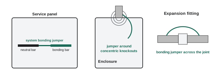
The system bonding jumper is the most important one, because it is the single point where the bonding system and the grounded conductor meet. Without it, a fault to a bonded enclosure has no path back to the source neutral, and the fault current has to return through the earth, with the results lesson 1 calculated. With a second connection somewhere downstream, normal neutral current divides between the neutral and the bonding path, putting current on raceways and enclosures where it should never be. Lesson 11 covers that error in detail.
The size of a field-installed system bonding jumper also comes from Table 16. Where the jumper is supplied with listed equipment, such as the bonding screw or strap in a panelboard, the manufacturer has sized it for the equipment's rating, and you use it as supplied.
Bonding conductors in parallel runs
When a large feeder is installed as several parallel sets of conductors, each in its own raceway or cable, each raceway or cable needs its own bonding path. Here a candidate's instinct is often wrong. It is tempting to divide the bonding conductor among the parallel runs, but a fault can occur on any one of them, and the fault current on that run returns through that run's bonding conductor alone, at least initially. Read the Code's provision on bonding conductors for parallel runs: the bonding conductor in each raceway or cable is sized from the rating of the overcurrent device protecting the whole feeder, not divided among the runs.
Worked problem
A parallel feeder at Riverbend
A 400 A feeder at Riverbend Condos is run as two parallel sets of conductors in two separate PVC raceways, each with its own copper bonding conductor. The feeder breaker is 400 A. Using practice table P-16, find the size code of the bonding conductor in each raceway.
Show solution
- Each raceway's bonding conductor is sized from the overcurrent device protecting the whole feeder: 400 A.
- 400 A falls in the band 301 to 400 A.
- Each raceway gets a B7 copper bonding conductor; the size is not halved because there are two runs.
Answer: B7 in each raceway (practice size).
Why the sizes work: the fault current check
Behind Table 16 is a simple physical idea: during a fault, the bonding conductor heats up, and it must not reach a temperature that damages its insulation or the insulation of conductors beside it before the device clears. Engineers check this with the adiabatic equation, which assumes the fault is so brief that no heat escapes. The Code does not ask you to do this calculation, but understanding it explains why a short clearing time permits a small conductor.
Here A is the conductor area in square millimetres, I the fault current in amperes, t the clearing time in seconds, and k a constant for the conductor material and its insulation. For copper with thermoplastic insulation, a commonly used engineering value is about 143. Larger currents and longer times need more copper; a fast device lets a modest conductor survive a very large fault.
Worked problem
Checking a bonding conductor
A fault of 6000 A on the Hartley Farms shop feeder is cleared by the 100 A breaker's instantaneous trip in 0.02 s. Using k = 143, find the minimum copper area needed to survive the fault, and compare it with a No. 8 AWG conductor of about 8.4 mm².
Show solution
- A = I √t / k = 6000 × √0.02 / 143.
- √0.02 ≈ 0.141, so A ≈ 6000 × 0.141 / 143 ≈ 5.9 mm².
- A No. 8 AWG copper conductor, at about 8.4 mm², is comfortably large enough for this fault and clearing time.
Answer: About 5.9 mm² minimum.
import math

def min_area(fault_a, seconds, k=143):
    return fault_a * math.sqrt(seconds) / k

for fault, t in [(6000, 0.02), (6000, 0.5), (20000, 0.05), (20000, 1.0)]:
print(f'{fault:6d} A for {t:4.2f} s needs at least {min_area(fault, t):6.1f} mm2 of copper')6000 A for 0.02 s needs at least 5.9 mm2 of copper 6000 A for 0.50 s needs at least 29.7 mm2 of copper 20000 A for 0.05 s needs at least 31.3 mm2 of copper 20000 A for 1.00 s needs at least 139.9 mm2 of copper
Run it and compare the second line with the first: the same fault current held for half a second instead of a fiftieth needs five times the area. That is why a fault that the breaker's instantaneous element clears is easy on the bonding path, and why slow clearing, such as a high-impedance arcing fault below the instantaneous setting, is dangerous.
Bonding conductor or raceway?
Not every circuit needs a separate bonding conductor. In many wiring methods, the metal raceway or cable armour is itself an acceptable bonding means, provided it is installed with the right fittings and maintained continuous. Rigid metal conduit, EMT with proper fittings and some armoured cables are examples. In other methods, such as non-metallic sheathed cable or non-metallic raceway, there is no metal path, and a separate bonding conductor is required. The Code's bonding methods rules and the wiring method rules in Section 12 decide which applies. Lesson 7 covers the methods, and lesson 8 the raceways, cables and piping.
Common mistakes
MistakeEntering Table 16 with the conductor ampacity or the calculated load instead of the overcurrent device rating.
InsteadFor circuits and feeders, use the rating or setting of the overcurrent device.
MistakeUsing the overcurrent device method at the service.
InsteadAt the service, size from the ampacity of the largest ungrounded service conductor, under 10-616(2).
MistakeDividing the bonding conductor among parallel runs.
InsteadEach parallel raceway or cable gets a bonding conductor sized from the whole feeder's overcurrent device.
MistakeForgetting the system bonding jumper, or adding a second one downstream.
InsteadThere must be exactly one system bonding jumper per system, at the service or source.
MistakeMaking the bonding conductor as large as the phase conductors without reason.
InsteadTable 16 sizes it for fault duty, which usually needs much less copper than the load conductors.
Summary and key terms
- Bonding conductors carry fault current for the short time the overcurrent device needs to clear.
- Rule 10-616 and Table 16 size bonding conductors from the overcurrent device rating, or from the largest service conductor ampacity at the service.
- The system bonding jumper is the single connection between the grounded conductor and the bonding system.
- Equipment bonding jumpers ensure continuity around knockouts, flexible sections, fittings and removable equipment.
- In parallel runs, each raceway or cable gets a bonding conductor sized for the whole feeder.
- Bonding conductor
- A conductor that connects non-current-carrying metal parts back to the service or source.
- System bonding jumper
- The connection between the grounded conductor and the bonding system at the service or source.
- Equipment bonding jumper
- A short conductor ensuring continuity between equipment or raceway parts.
- Adiabatic equation
- A relationship between fault current, clearing time and the conductor area that survives it.
- Table 16
- The Code table for minimum sizes of bonding conductors and field-installed system bonding jumpers.
Practice problems
Work each problem on paper first, then reveal the answer to check.
A 60 A breaker protects a feeder with 75 A conductors. What do you enter Table 16 with?
Show answer
60 A, the breaker rating.
A 600 A feeder runs as three parallel sets in three raceways. What do you size each raceway's bonding conductor from?
Show answer
The 600 A overcurrent device, for each raceway.
Find the minimum copper area for 10 000 A cleared in 0.04 s with k = 143.
Show answer
10 000 × 0.2 / 143 ≈ 14.0 mm².
What is the everyday name of the system bonding jumper at a service?
Show answer
The main bonding jumper.
Lesson quiz · 5 questions
Score 60% or more to complete this lesson.
Create a free account to save your progress, take quizzes and earn a certificate.