
MELC-104 · Lesson 1 of 12 · 25 min
Why we ground and why we bond
▶ Video coming soon A video version of this lesson is on the way.
Grounding and bonding questions appear on every Canadian master electrician exam, and they are the questions candidates most often get wrong. Not because the rules are especially long, but because the words are slippery. Grounding, bonding, grounded conductor, grounding conductor, bonding conductor, bonding jumper: these sound alike, and a candidate who mixes them up will look up the wrong rule, read the wrong table and choose the wrong size. This course untangles them. It covers Section 10 of the CE Code Part I, the section that tells you how electrical systems are connected to the earth and how all the metal around them is tied together so that a fault clears quickly and nobody gets a shock.
This first lesson is about purpose. Before any rule or table, you need a clear picture of what grounding does and what bonding does, because nearly every Section 10 requirement makes sense once you can see which job it serves. Exam writers know this. Many of their questions are written so that a candidate who understands the purpose can reason to the answer even without finding the rule, and a candidate who has memorized a table without understanding it falls into the trap.
As in the rest of the MELC series, this course never reproduces the text, tables or figures of the CE Code. When a lesson refers to a rule or a table, it gives the number and explains the idea in its own words. Any values shown in worked examples or practice tables are illustrative, invented for teaching, and you must always check the real values in your own copy of the 2024 CE Code Part I and any amendments your province has adopted.
Tuesday night in Red Deer
The study group from MELC-101 and MELC-102 is back. Priya Raman, the Red Seal lead hand at Parkland Valley Electric in Red Deer, is fourteen weeks out from her Alberta Master Electrician Certificate exam. Marcus Okafor, her study partner, spent years on oil sands shutdowns and knows motor control cold. Denise Lafleur, the retired safety codes officer who runs the Tuesday-night group, has seen more grounding mistakes than she can count. Tyler Chen, the third-year apprentice, is there because Gord Tremblay, the owner, thinks apprentices learn more at a study table than on a ladder.
Denise starts with a question she says she asked on hundreds of inspections. She holds up a ground rod and asks Tyler what it is for. Tyler says it is so the breaker trips when something shorts to the case. Denise smiles and writes on the whiteboard: a 120 V circuit, a ground rod with a resistance of 25 ohms, a 15 A breaker. If a hot conductor touches a metal case that is connected only to that rod, how much current flows? Tyler works it out. About 4.8 A. The breaker never trips, and the case sits at nearly 120 V for as long as the fault lasts. The rod did not clear the fault. Something else has to.
That something else is bonding: a low-impedance metal path from every exposed conductive part back to the source, so that a fault becomes a short circuit large enough to operate the overcurrent device in a fraction of a second. Grounding to the earth has its own jobs, but clearing faults is mostly bonding's job. Denise wants every member of the group to be able to say that sentence before they open the Code.
What grounding does
Grounding means connecting a part of the electrical system, usually the neutral or another designated conductor, to the earth through a grounding electrode. In Code language, the connection is made with a grounding conductor, and the conductor that is intentionally connected to ground is the grounded conductor. Grounding serves several purposes, and it helps to keep them separate.
- It limits the voltage to ground. Without a deliberate connection, the system floats, and its voltage relative to the earth is set by stray capacitance and leakage. A grounded system has a known, stable voltage to ground, for example 120 V on a 120/240 V system or 347 V on a 347/600 V system.
- It limits voltages from outside events. Lightning, switching surges on the utility system and accidental contact between a primary line and the secondary can all impose high voltages on a building's wiring. A connection to earth gives those voltages a place to go and limits how high they rise.
- It stabilizes the system during normal operation, so that insulation is not stressed beyond its rating and equipment sees the voltage it was designed for.
- It provides a reference for ground fault detection and protection. Ground fault circuit interrupters and ground fault protection on large services depend on a defined grounded point.
Look at what is missing from that list: clearing ordinary faults inside the building. The earth is a poor conductor compared with copper, and the resistance of a typical electrode is measured in ohms or tens of ohms. That is fine for limiting voltage, because limiting voltage needs very little current. It is useless for operating a breaker, because operating a breaker needs hundreds of amperes.
What bonding does
Bonding means connecting the non-current-carrying metal parts of an installation together, and back to the grounded conductor at the service or source, with a conductor or a metal path of low impedance. Raceways, boxes, enclosures, equipment frames, metal piping and building steel are all bonded. The purposes are just as specific.
- It provides an effective fault current path. If an ungrounded conductor faults to a bonded enclosure, the fault current flows through the bonding path back to the source and returns on the grounded conductor. The loop impedance is low, the current is high, and the overcurrent device opens quickly.
- It keeps exposed metal at the same potential. Two metal parts that are bonded together cannot have a dangerous voltage between them, even during a fault, because the bonding conductor holds them close to the same voltage. A person touching both is not part of the circuit.
- It limits touch voltage during a fault. Even a well-bonded enclosure rises in voltage briefly while fault current flows, because of the voltage drop along the bonding path. The lower the impedance, the lower that rise and the shorter its duration.
The two ideas meet at one point. At the service, the grounded conductor, the bonding path and the grounding conductor to the electrode are all connected together. That connection, made through what the Code calls a bonding jumper at the service, is what lets the bonding path deliver fault current back to the source, and what ties the whole bonded system to earth. Lesson 6 covers the jumpers in detail. For now, remember that the bonding path is designed to carry fault current, and the earth connection is not.
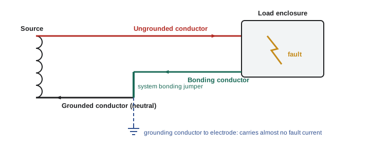
The fault loop in numbers
Every fault question on an exam comes down to the same loop: the source, the ungrounded conductor out to the fault, the fault itself, the bonding path back, and the source winding that closes the circuit. The fault current is the source voltage divided by the total impedance of that loop. At the levels of detail used on licensing exams, you can treat the impedances as resistances and add them.
Worked problem
Bonded fault versus rod-only fault
A 120 V branch circuit at the Aspen Ridge bungalow has a line conductor resistance of 0.15 Ω for the run to a metal box. The source and service impedance is 0.05 Ω. In case A, the box is properly bonded and the bonding path has a resistance of 0.20 Ω. In case B, an installer has left the bonding conductor off, and the box is connected to earth only through a separate rod of 25 Ω, with the service electrode at 15 Ω. Find the fault current in each case.
Show solution
- Case A: total loop resistance = 0.05 + 0.15 + 0.20 = 0.40 Ω. Fault current = 120 / 0.40 = 300 A. A 15 A breaker clears this almost instantly.
- Case B: the return path is through earth: 0.05 + 0.15 + 25 + 15 = 40.2 Ω. Fault current = 120 / 40.2 ≈ 3.0 A.
- In case B the breaker never trips, and the box stays energized at a dangerous voltage until someone notices.
Answer: About 300 A with a proper bond; about 3 A through the earth alone.
That example is the single most important calculation in this course. It explains why the Code insists on a continuous metal bonding path for every circuit, and why a separate ground rod at a piece of equipment is never a substitute for a bonding conductor. Exam writers love to offer a rod as a tempting wrong answer.
Touch voltage
During a bonded fault, current flows through the bonding path, and the bonding path has some resistance. The voltage drop along it appears on the faulted enclosure relative to the service and the earth near the service. That is the touch voltage a person would feel if they touched the enclosure while standing on the ground. A larger bonding conductor and a shorter run mean less voltage, and a faster-clearing device means less time at that voltage. Both matter, because the danger of a shock depends on current through the body and on how long it lasts.
Worked problem
Touch voltage on the bonded box
Using case A above, find the voltage on the faulted box relative to the service.
Show solution
- Fault current = 300 A. Bonding path resistance = 0.20 Ω.
- Touch voltage ≈ 300 × 0.20 = 60 V.
- The voltage is not zero, but it lasts only for the few milliseconds the breaker needs to open.
Answer: About 60 V, for a very short time.
This is why bonding conductors are sized from the overcurrent device protecting the circuit and not from the normal load current. A bonding conductor carries no current at all in normal operation, so it has no load to size it by. It has to carry the fault current long enough for the device to clear, without overheating and without letting the touch voltage rise too high. Lesson 6 follows that logic through the Code's bonding conductor table.
def fault(v, r_source, r_line, r_return):
    i = v / (r_source + r_line + r_return)
    return i, i * r_return

cases = [
    ('Proper bonding conductor', 0.20),
    ('Undersized bonding conductor', 0.60),
    ('Earth return only (rods)', 40.0),
]
for name, r_ret in cases:
    i, vt = fault(120, 0.05, 0.15, r_ret)
print(f'{name:30s} fault {i:7.1f} A touch voltage {vt:6.1f} V')Proper bonding conductor fault 300.0 A touch voltage 60.0 V Undersized bonding conductor fault 150.0 A touch voltage 90.0 V Earth return only (rods) fault 3.0 A touch voltage 119.4 V
Edit the return resistance and watch how quickly the fault current collapses once the earth becomes part of the path. Then notice that the touch voltage on the rod-only case is nearly the full 120 V, held indefinitely, because nothing trips.
Why the earth is not a return path
A common misunderstanding, even among experienced electricians, is that current wants to go to ground. It does not. Current returns to its source. The earth becomes part of a circuit only when it is the easiest path back to the source, and for faults inside a building it almost never is. The source of a building's supply is the utility transformer's secondary winding, and the neutral of that winding is connected to the building's grounded conductor. The way back to that winding is along the metal conductors, not through the soil.
Denise tells the group about a call she attended at a rural property where a homeowner had wired a detached workshop with a two-wire feeder and driven a ground rod at the shop for the equipment bonding. A table saw developed a fault to its frame. The saw kept running, the breaker never tripped, and the homeowner got a shock every time he touched the saw and the metal bench together. The rod had a resistance of about 40 Ω in dry gravel. The fix was not a better rod but a proper bonding conductor back to the house panel with the feeder, the arrangement lesson 10 covers in detail.
Lightning, surges and the earth connection
The earth connection earns its place in other ways. When lightning strikes near a building or on the utility lines, the surge travels along the conductors looking for a way to the earth. A well-made electrode and grounding conductor give it a defined route, so it does not jump through insulation, flash across a panel or travel through someone's appliances. Surge protective devices depend on that connection too.
The electrode also matters if a primary conductor on the utility system ever contacts the secondary. Without a solid connection to earth, the secondary system could rise to thousands of volts relative to the ground a person is standing on. With it, the voltage rise is limited and the utility's protection is more likely to operate. Those events are rare, but they are exactly the events grounding exists for.
| Function | Done mainly by | Typical current involved |
|---|---|---|
| Limit voltage to earth | Grounding (electrode connection) | Very small in normal operation |
| Divert lightning and surges | Grounding and surge devices | Very large, very brief |
| Clear faults quickly | Bonding path back to the source | Hundreds to thousands of amperes |
| Keep metal at equal potential | Bonding between parts | Small, except during faults |
| Enable ground fault detection | Defined grounded point plus bonding | Milliamperes to amperes |
How the purposes show up on the exam
Master exams test these ideas in three main ways. The first is direct: a question asks what the purpose of bonding is, or which statement about grounding electrodes is true. The second is applied: a question describes an installation and asks whether it is acceptable, and the answer depends on recognizing that a rod is standing in for a bonding conductor, or that a neutral has been bonded to an enclosure somewhere other than the service. The third is calculation: fault current, touch voltage, voltage to ground or a conductor size whose logic comes straight from the purpose.
Priya keeps a one-line purpose note at the top of her Section 10 tab: grounding limits voltage; bonding clears faults and equalizes metal. When a question confuses her, she reads that line first and asks which job the question is really about. Marcus thinks it is too simple. Denise says simple is the point. The Code is written in long sentences, and the purpose is what keeps you from getting lost in them.
Looking ahead
The rest of the course follows the structure of Section 10. Lesson 2 maps the section and its definitions. Lesson 3 explains which systems must be solidly grounded and which may be ungrounded or impedance grounded. Lessons 4 and 5 cover grounding electrodes and grounding conductors. Lessons 6 to 8 cover bonding conductors, bonding methods and the bonding of raceways, cables and piping. Lessons 9 and 10 deal with the two situations that cause the most confusion in practice: separately derived systems and separate buildings. Lesson 11 collects the errors inspectors find most often, and lesson 12 is a practice set built the way exam questions are built.
Common mistakes
MistakeBelieving a ground rod will make a breaker trip on a fault to a metal case.
InsteadFault clearing depends on a low-impedance bonding path back to the source; earth resistance is far too high.
MistakeSaying current wants to go to ground.
InsteadCurrent returns to its source; the earth is a path only when it is the easiest one back.
MistakeSizing a bonding conductor from the normal load current.
InsteadA bonding conductor carries no normal current; it is sized for fault duty from the overcurrent device.
MistakeTreating grounding and bonding as the same thing.
InsteadGrounding connects the system to earth to limit voltage; bonding ties metal parts together and back to the source to clear faults.
MistakeDriving a separate rod at equipment instead of running a bonding conductor.
InsteadRun a bonding conductor with the circuit; a supplementary rod never replaces it.
Summary and key terms
- Grounding connects a system conductor to earth to limit and stabilize voltage and to divert surges.
- Bonding ties non-current-carrying metal together and back to the source to clear faults and keep metal at equal potential.
- Fault current equals source voltage divided by the total loop impedance, so the bonding path must be low impedance.
- Earth resistance is measured in ohms, so an earth-only return path lets faults persist without tripping the breaker.
- Touch voltage is roughly fault current times bonding path resistance, and it lasts until the device clears.
- Grounding
- A connection of a system conductor or equipment to the earth through a grounding electrode.
- Bonding
- A low-impedance connection between non-current-carrying conductive parts, and back to the grounded conductor at the source.
- Fault current path
- The route fault current takes from the point of fault back to the source.
- Touch voltage
- The voltage between an exposed conductive part and the ground a person stands on, during a fault.
- Grounded conductor
- A system conductor intentionally connected to ground, usually the neutral.
Practice problems
Work each problem on paper first, then reveal the answer to check.
A 240 V fault has a loop resistance of 0.6 Ω. Find the fault current.
Show answer
I = 240 / 0.6 = 400 A.
A 120 V fault returns through rods totalling 30 Ω plus 0.2 Ω of wiring. Find the current.
Show answer
120 / 30.2 ≈ 4.0 A, far too small to trip a 15 A breaker.
A fault of 500 A flows through a bonding path of 0.08 Ω. Find the touch voltage.
Show answer
500 × 0.08 = 40 V for the clearing time.
State the main purpose of grounding a system to earth.
Show answer
To limit and stabilize the voltage to earth, including during surges and lightning.
Lesson quiz · 5 questions
Score 60% or more to complete this lesson.
Create a free account to save your progress, take quizzes and earn a certificate.