
MELC-104 · Lesson 4 of 12 · 24 min
Grounding electrodes and their installation
▶ Video coming soon A video version of this lesson is on the way.
A grounding electrode is the physical connection between an electrical system and the earth. It might be a pair of copper-clad steel rods driven beside the foundation, a buried plate, a length of bare copper laid in the footing trench, or a piece of existing metal infrastructure that happens to be in excellent contact with the soil. Section 10 sets out which electrodes are permitted, how they are installed, how several electrodes at the same building are tied together, and how the grounding conductor connects to them.
Electrode questions on master exams are a mix of lookup and understanding. You may be asked which kinds of electrode are permitted, how many rods are required and how far apart, how deep a plate must be buried, or what to do when rock prevents a rod from being driven. You may also be asked conceptual questions: why two rods side by side are not twice as good as one, why the resistance of an electrode changes with the seasons, or why the electrodes for a communication system must be bonded to the power system electrode. This lesson covers both kinds.
The dimensions, depths and spacings in the Code's electrode rules are not reproduced here. Where the lesson mentions a commonly applied arrangement, treat it as a pointer to the rule, and check the actual requirement, and any provincial amendment, in your own 2024 CE Code.
At the Aspen Ridge site
Parkland Valley Electric is roughing in the service at the Aspen Ridge bungalow, and Priya takes Tyler out to watch the electrodes go in. The soil is the heavy clay typical of central Alberta, and the rods drive easily for the first metre and then slowly. Tyler asks why they are driving two rods when the old farmhouse down the road has one. Priya says the old house was wired to a much older code, and that one rod in dry soil can have a resistance that would surprise him. They take a reading later with a clamp-on tester and find about 30 ohms on the first rod alone.
At the Tuesday group, Denise uses that reading to start the electrode lesson. Thirty ohms, she says, is not unusual for a single rod. It is perfectly adequate for what an electrode is for, limiting the system's voltage to earth and giving surges somewhere to go, and completely inadequate for clearing faults, which is not what an electrode is for. Lesson 1 again, she says. Keep the jobs straight.
The kinds of electrode
The 2024 Code groups permitted grounding electrodes into three broad families. Learn the families first; the details of each are in the electrode rules.
- Manufactured electrodes. Products made and certified for use as electrodes: ground rods, typically copper-clad steel or stainless steel, and ground plates. The Code sets minimum dimensions and the number required, and the installation rules set depth and spacing.
- Field-assembled electrodes. Electrodes built on site from approved materials, such as a length of bare copper conductor buried in the earth around a building or laid in the concrete of a footing, or a grid or ring of conductor. The Code sets the minimum conductor size, length and burial or encasement requirements.
- In-situ electrodes. Existing metal infrastructure that is in intimate contact with the earth, such as certain metal water piping systems, metal well casings or other buried metal structures, used as an electrode where the Code permits and under the conditions it sets.
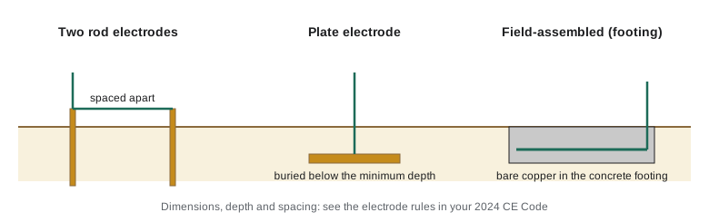
On new construction, a field-assembled electrode in the footing is often the best electrode on the site, because concrete in contact with the earth holds moisture and has a large contact area. It has to be planned before the concrete is poured, which means the electrical contractor talking to the foundation contractor early. Denise has seen many jobs where the opportunity was missed and the electrician arrived to find the footings already backfilled.
Installing rods and plates
Rod electrodes are commonly installed as a pair, driven to their full length and spaced apart so that their zones of influence in the soil do not overlap too much, with the two joined by the grounding conductor. Where rock prevents a rod from being driven vertically, the Code provides alternatives, such as driving at an angle or laying the electrode in a trench, subject to conditions. Plates are buried below a minimum depth so that they stay in moist soil below the surface layer. The top of a rod is normally flush with or below grade, protected from damage, and the connection to it uses a method approved for direct burial.
Read the electrode installation rules closely for three things that exams like to test: the minimum number of rod electrodes, the minimum spacing between them, and what to do when they cannot be driven to full depth. Then read the rule on interconnecting electrodes, because it answers another favourite question: what happens when a building has several electrodes for different purposes.
Why two rods are not twice as good as one
Current leaving a rod spreads out through the soil in all directions. Most of the resistance of an electrode is in the soil immediately around it, where the current is concentrated into a small volume. As you move away from the rod, the current spreads over a larger area and the resistance per metre falls. That is why the resistance depends so strongly on the rod's length and much less on its diameter: a longer rod reaches more soil.
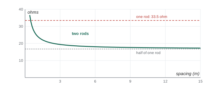
When two rods are close together, their current fields overlap, and each rod is partly pushing current into soil the other is already using. The combined resistance is lower than one rod, but not half. Spread them farther apart and the result gets closer to half. A common rule of thumb is that rods spaced at least their own length apart give most of the benefit, which is one reason the Code sets a minimum spacing.
The formula above, a standard approximation for a single driven rod, uses the soil resistivity ρ in ohm-metres, the rod length L and the rod radius a, both in metres. You will not need to memorize it for a licensing exam, but working one example builds the intuition behind the electrode rules.
Worked problem
One rod and two
A rod 3 m long with a radius of 8 mm is driven in soil with a resistivity of 100 Ω·m. Estimate its resistance. Then estimate the resistance of two such rods spaced 3 m apart, using the approximation R_pair ≈ (R_rod + R_m) / 2, where the mutual term R_m ≈ ρ / (2π s) and s is the spacing.
Show solution
- ln(4L / a) = ln(12 / 0.008) = ln(1500) ≈ 7.31.
- ρ / (2πL) = 100 / (2π × 3) ≈ 5.31 Ω.
- R_rod ≈ 5.31 × (7.31 − 1) ≈ 33.5 Ω.
- R_m ≈ 100 / (2π × 3) ≈ 5.3 Ω.
- R_pair ≈ (33.5 + 5.3) / 2 ≈ 19.4 Ω, not 16.8 Ω as simple halving would suggest.
Answer: About 33.5 Ω for one rod and about 19.4 Ω for the pair.
import math

def rod(rho, length, radius):
    return rho / (2 * math.pi * length) * (math.log(4 * length / radius) - 1)

def pair(rho, length, radius, spacing):
    return (rod(rho, length, radius) + rho / (2 * math.pi * spacing)) / 2

rho = 100
print(f'one rod, 3 m:       {rod(rho, 3.0, 0.008):5.1f} ohm')
for s in (1.0, 3.0, 6.0, 12.0):
print(f'two rods {s:4.1f} m apart: {pair(rho, 3.0, 0.008, s):5.1f} ohm')one rod, 3 m: 33.5 ohm two rods 1.0 m apart: 24.7 ohm two rods 3.0 m apart: 19.4 ohm two rods 6.0 m apart: 18.1 ohm two rods 12.0 m apart: 17.4 ohm
Run it and watch the pair's resistance approach half of a single rod as the spacing grows. Then change the soil resistivity to 500, a reasonable figure for dry gravel, and see why an electrician in the foothills might measure a rod resistance well over a hundred ohms.
Soil, moisture and seasons
Soil resistivity varies enormously: from a few ohm-metres in wet clay or salty soil to thousands in dry sand, gravel or rock. It also varies with moisture and temperature. Frozen soil has a much higher resistivity than the same soil in summer, which matters in Alberta, where frost can reach well over a metre deep. An electrode that measures 20 Ω in August might measure 60 Ω in February. Longer rods and footing electrodes are less affected, because they reach soil below the frost line.
The resistivity of a site can be measured with a four-pin method, in which current is injected through two outer pins and voltage is measured between two inner pins. The result, combined with the pin spacing, gives the apparent resistivity of the soil to a depth related to that spacing. Designers of large installations measure it; electricians wiring houses rarely do. Exam questions occasionally test the principle.
Worked problem
A four-pin reading
A four-pin test at Hartley Farms, with pins spaced 3 m apart, gives a resistance reading of 4.2 Ω. Estimate the soil resistivity.
Show solution
- ρ = 2π × a × R = 2π × 3 × 4.2.
- ρ ≈ 79 Ω·m.
Answer: About 79 Ω·m, moderately conductive soil.
Interconnecting electrodes
A modern building often has several electrodes: the power system electrode, perhaps a separate electrode installed by the telephone or cable company, a lightning protection system, a radio antenna ground, or an electrode for a separately derived system. If these are left separate, a lightning strike or a power fault can raise one electrode's voltage relative to the others, and that voltage difference appears across any equipment connected to two systems at once. A television connected to both the power system and a cable system with its own separate ground is a classic victim.
The Code's rule on interconnection requires electrodes at a building for different purposes to be bonded together, so that all of them rise and fall together. It sets out how the bonding is made and the minimum size of the bonding conductor between them. On the exam, the key idea is simple: all the electrodes at a building must be interconnected, with the exceptions and conditions the rule describes.
Worked problem
The voltage between two separate electrodes
During a nearby lightning strike, the power system electrode at a rural home rises to 3000 V relative to remote earth while a separate, unbonded antenna electrode rises to only 400 V. A television is connected to both the power system and the antenna. What voltage appears across the television's internal insulation between the two systems?
Show solution
- The difference between the two electrode voltages appears between the power wiring and the antenna wiring.
- 3000 − 400 = 2600 V across the television.
- If the two electrodes were bonded together, they would rise together and the difference would be small.
Answer: About 2600 V, enough to destroy the set and start a fire.
Connecting to the electrode
The grounding conductor connects to the electrode with a method suited to the location: clamps listed for direct burial, compression connectors or exothermic welds. The connection must be accessible where the rules require it, protected where it could be damaged, and made so that it will not loosen or corrode. On a pair of rods, the grounding conductor typically runs from the service to the first rod and on to the second without a splice, or is connected in a way the Code permits. Lesson 5 covers the grounding conductor's size and installation in detail.
Tyler notices the clamp Priya uses on the rods has a marking on it. Priya explains that the marking shows the clamp is approved for direct burial, which matters because a clamp buried in wet clay for forty years will corrode if it is the wrong material. Denise adds that inspectors look for that marking, and that the right clamp costs a few dollars more than the wrong one.
Testing electrodes
The Code does not generally set a maximum resistance for an ordinary building electrode, which surprises many candidates who learned from American sources that mention a 25 Ω figure. Some utilities, provinces or specifications do set targets, and some supplementary sections have their own requirements. Testing methods include the fall-of-potential method, which uses temporary test stakes driven at measured distances, and the clamp-on method, which measures the resistance of an electrode that is part of a larger interconnected system. Each method has limitations, and each gives a result that varies with season and moisture. If an exam asks for a maximum electrode resistance, check whether the question is about a supplementary section or a specific standard before answering.
Common mistakes
MistakeExpecting two rods side by side to give half the resistance of one.
InsteadOverlapping current fields mean the pair is better than one rod but worse than half; spacing matters.
MistakeTreating a single rod's resistance as adequate to clear faults.
InsteadElectrodes limit voltage and divert surges; fault clearing depends on the bonding path.
MistakeLeaving separate electrodes for communication or lightning systems unbonded.
InsteadInterconnect all electrodes at a building as the Code requires.
MistakeUsing an indoor-rated clamp on a buried rod.
InsteadUse a connector approved for direct burial.
MistakeQuoting a general maximum resistance for building electrodes from another country's code.
InsteadCheck what the CE Code, the province and any supplementary section actually require.
Summary and key terms
- The Code permits manufactured electrodes (rods and plates), field-assembled electrodes and in-situ electrodes under set conditions.
- Rods are commonly installed in pairs, driven full length and spaced apart; rock and depth alternatives are covered by the rules.
- Two rods give less than half the resistance of one unless they are widely spaced, because their current fields overlap.
- Soil resistivity varies with soil type, moisture and frost, so electrode resistance changes with the seasons.
- All electrodes at a building, for whatever purpose, must be interconnected so they rise and fall together.
- Grounding electrode
- A conductive object in intimate contact with the earth, providing the system's connection to ground.
- Soil resistivity
- The resistance of a unit cube of soil, in ohm-metres; it governs electrode resistance.
- Field-assembled electrode
- An electrode built on site from approved materials, such as bare copper in a footing.
- In-situ electrode
- Existing buried metal infrastructure used as an electrode where the Code permits.
- Fall-of-potential test
- A method of measuring electrode resistance using temporary test stakes.
Practice problems
Work each problem on paper first, then reveal the answer to check.
Estimate the resistance of a 3 m rod with 8 mm radius in 200 Ω·m soil.
Show answer
Twice the 100 Ω·m value: about 67 Ω.
A four-pin test with 2 m spacing reads 10 Ω. Find the resistivity.
Show answer
ρ = 2π × 2 × 10 ≈ 126 Ω·m.
Why must a cable television electrode be bonded to the power electrode?
Show answer
So both rise together in a surge, avoiding a large voltage between the two systems at connected equipment.
Name the three families of permitted electrodes.
Show answer
Manufactured, field-assembled and in-situ.
Lesson quiz · 5 questions
Score 60% or more to complete this lesson.
Create a free account to save your progress, take quizzes and earn a certificate.