
MELC-104 · Lesson 3 of 12 · 25 min
Solidly grounded and ungrounded systems
▶ Video coming soon A video version of this lesson is on the way.
Every electrical system falls into one of three groups according to how it is connected to ground. A solidly grounded system has one of its conductors, usually the neutral, connected directly to ground with no intentional impedance. An impedance grounded system is connected to ground through a resistor or reactor that deliberately limits the current of a ground fault. An ungrounded system has no intentional connection to ground at all. Each choice has consequences for safety, for continuity of service and for how faults behave, and Section 10 has rules for each.
Exam questions on this topic tend to come in two forms. The first asks whether a particular system must be solidly grounded, may be ungrounded, or may be impedance grounded, and the answer comes from a short rule with a couple of tests. The second asks what happens during a ground fault on each kind of system: how much current flows, what voltage the unfaulted conductors rise to, and what detection must be provided. This lesson covers both.
The lesson paraphrases the requirements; read the rules on system grounding in your own 2024 CE Code Part I, along with the definitions in Section 0.
Marcus's question
Marcus brings a story from the oil sands to the study group. On one shutdown, a motor cable faulted to ground on a 600 V distribution system, and nothing tripped. The plant kept running, an alarm lit in the control room, and the maintenance crew found and fixed the fault on the next day shift. On his next job, at a commercial building, a similar cable fault on a 347/600 V system tripped a feeder breaker instantly and shut down half the building. Same voltage, same kind of fault, completely different result. Why?
The answer is the way each system was grounded. The plant used a high-resistance grounded system, where a resistor limits a ground fault to a few amperes, too little to trip a breaker but enough to detect. The commercial building used a solidly grounded wye system, where a ground fault is effectively a short circuit. Denise says that one story explains the whole lesson, and she builds the evening around it.
Which systems must be solidly grounded
The CE Code requires an alternating-current system operating above extra-low voltage to be solidly grounded in two situations: where the system can be grounded so that the maximum voltage to ground does not exceed 150 V, and where the system includes a neutral conductor. Subrule 10-206(1) is the place to read this, and its two tests are among the most frequently examined ideas in Section 10.
Apply the tests to the systems you meet every day:
- 120/240 V single-phase, three-wire: grounding the centre tap gives 120 V to ground, which is under 150 V, and the system has a neutral. It must be solidly grounded.
- 120/208 V three-phase, four-wire wye: grounding the neutral gives 120 V to ground, and the system has a neutral. It must be solidly grounded.
- 347/600 V three-phase, four-wire wye: the voltage to ground is 347 V, so the first test is not met, but the system includes a neutral conductor, so the second test is. It must be solidly grounded.
- 600 V three-phase, three-wire delta or wye without a neutral: the voltage to ground would exceed 150 V and there is no neutral. Neither test is met, so the system is not required to be solidly grounded. It may be solidly grounded, impedance grounded or ungrounded, subject to the other rules.
Think about the role of the neutral. A 347/600 V system is required to be solidly grounded not because of its voltage but because it carries 347 V loads, such as lighting, between a phase and the neutral. If the neutral were left floating, a fault could shift the neutral's voltage and put far more than 347 V across those loads. Solid grounding pins the neutral at earth potential and keeps phase-to-neutral voltages stable.
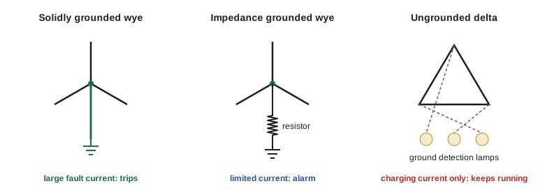
How a solidly grounded system behaves in a fault
On a solidly grounded system, a ground fault on a phase conductor creates a low-impedance loop through the bonding path back to the grounded neutral at the source. The fault current is large, typically hundreds or thousands of amperes, and the overcurrent device opens quickly. That is the main advantage of solid grounding: faults clear themselves, and exposed metal does not stay energized.
The disadvantage is that every ground fault interrupts service. On a commercial or residential system, that is exactly what you want. In some industrial processes, an unplanned shutdown can be dangerous or very costly, which is why other grounding methods exist. A second disadvantage on large solidly grounded systems is arcing ground faults: an arc can have enough impedance to limit current below the trip setting of a large breaker while still doing serious damage. Ground fault protection on large services, covered by other Code rules, exists to catch those faults.
Worked problem
Solidly grounded fault current
At the Gaetz Avenue dental clinic, a 120/208 V feeder faults to a bonded enclosure. The phase-to-neutral voltage is 120 V, and the total loop impedance, including the transformer, the phase conductor and the bonding path, is 0.08 Ω. Find the fault current.
Show solution
- The fault is phase to bonded metal, so the driving voltage is the phase-to-neutral voltage, 120 V.
- I = 120 / 0.08 = 1500 A.
- Any breaker in the circuit sees a current many times its rating and clears quickly.
Answer: 1500 A.
Ungrounded systems
An ungrounded system has no deliberate connection between any of its conductors and ground. It is not truly isolated, because every conductor has capacitance to ground through its insulation, and that capacitance holds the system roughly balanced around earth potential. But no conductor is tied to ground.
When one phase of an ungrounded system faults to ground, very little current flows. The only return path is through the capacitance of the other two phases, which gives a small charging current, often well under an ampere on a small system. The overcurrent devices do not see a fault, and the system keeps running. That is the attraction: one ground fault does not shut anything down.
The price is in the voltages. With phase A solidly faulted to ground, phase A is now at earth potential, so phases B and C are at the full line-to-line voltage relative to earth. On a 600 V ungrounded system, the unfaulted phases rise from about 347 V to ground to 600 V to ground. Insulation everywhere on the system is now stressed at the full line voltage, and a second fault on another phase, anywhere on the system, becomes a phase-to-phase fault through the earth and the bonding path, with large currents and possibly in two different pieces of equipment at once.
Ungrounded systems are also vulnerable to transient overvoltages from intermittent arcing faults, where repeated restriking can charge the system capacitance to several times normal voltage. For those reasons, where the Code allows an ungrounded system, it requires ground detection, so that the first fault is found and repaired before a second one occurs. The rules on ungrounded systems in Section 10 set out the detection requirements; a common arrangement is a set of three lamps or a voltmeter scheme that shows which phase has gone to ground.
Worked problem
Voltages on an ungrounded system
Hartley Farms has an old 600 V three-wire delta system feeding the grain-drying motors. Phase A faults solidly to the frame of a motor. Assuming the system was balanced before the fault, find the voltage to ground of phases B and C before and after the fault.
Show solution
- Before the fault, a balanced ungrounded system sits roughly symmetrical around earth: each phase is about 600 / 1.732 = 346 V to ground.
- After the fault, phase A is at earth potential.
- Phases B and C are each at the full line-to-line voltage, 600 V, relative to earth.
Answer: About 346 V before; 600 V after.
Impedance grounded systems
An impedance grounded system sits between the other two. The neutral of a wye source, or a neutral derived with a grounding transformer on a delta system, is connected to ground through a resistor or reactor. When a phase faults to ground, the fault current flows through that impedance, which limits it to a chosen value.
High-resistance grounding, the arrangement Marcus met in the oil sands, limits ground fault current to a few amperes. It keeps the operational advantage of the ungrounded system, because a single ground fault does not trip anything, while avoiding the transient overvoltages, because the resistor drains the system capacitance. It also makes faults easy to locate: the fault current is known and steady, and a portable sensor can trace it. Low-resistance grounding, used mainly on higher-voltage systems, limits fault current to hundreds of amperes, enough to trip protective relays but far less than a solid fault.
The Code's rules for impedance grounded systems cover the neutral grounding device itself, its rating and continuous-duty capability, ground fault detection and alarms, and restrictions on connecting line-to-neutral loads. That last point connects back to the solid grounding rule: a system that serves line-to-neutral loads has a neutral and must be solidly grounded, so high-resistance grounding is used on three-wire systems feeding three-phase loads such as motors.
Worked problem
Sizing a neutral grounding resistor
A 600 V three-phase, three-wire system at a processing plant is to be high-resistance grounded with the ground fault current limited to 5 A. Find the resistance of the neutral grounding resistor.
Show solution
- The resistor sits between the neutral of the wye source and ground, so a solid phase-to-ground fault puts the phase-to-neutral voltage across it.
- V_LN = 600 / 1.732 = 346 V.
- R = 346 / 5 = 69.3 Ω.
Answer: About 69 Ω.
A design check that appears in exam questions: the resistor's let-through current should be at least as large as the system's total capacitive charging current. If it is smaller, the resistor cannot fully damp the transient overvoltages that the arrangement is supposed to prevent. The charging current depends on the cable lengths and the equipment connected, and it is usually measured or estimated for each system.
import math

def ngr(v_ll, i_set):
    v_ln = v_ll / math.sqrt(3)
    return v_ln, v_ln / i_set, v_ln * i_set

for v_ll, amps in [(600, 5), (600, 2), (4160, 10)]:
    v_ln, ohms, watts = ngr(v_ll, amps)
print(f'{v_ll:5d} V system, {amps:3d} A: {v_ln:7.1f} V across, {ohms:7.1f} ohm, {watts/1000:6.2f} kW during a fault')600 V system, 5 A: 346.4 V across, 69.3 ohm, 1.73 kW during a fault 600 V system, 2 A: 346.4 V across, 173.2 ohm, 0.69 kW during a fault 4160 V system, 10 A: 2401.8 V across, 240.2 ohm, 24.02 kW during a fault
The last column shows the power the resistor dissipates during a sustained fault. Because a high-resistance grounded system is designed to keep running with a ground fault present, the resistor must be rated to carry its current continuously, which is one of the points the Code addresses for neutral grounding devices.
Corner-grounded delta
One more arrangement appears now and then on exams and in older industrial buildings: the corner-grounded delta, where one phase of a three-wire delta system is solidly grounded. It is a solidly grounded system, so ground faults on the other two phases trip quickly, but the grounded phase is not a neutral, and it must be identified and treated according to the Code's rules for grounded conductors. Voltage to ground on the other two phases is the full line-to-line voltage. It is uncommon in new work but useful to recognize.
| Arrangement | First ground fault | Voltage to ground of unfaulted phases | Detection needed |
|---|---|---|---|
| Solidly grounded wye | Large current; device trips | Stays near phase-to-neutral | Overcurrent device; ground fault protection on large services |
| High-resistance grounded wye | A few amperes; keeps running | Rises to line-to-line | Yes: alarm and location |
| Ungrounded delta or wye | Charging current only; keeps running | Rises to line-to-line | Yes: ground detection |
| Corner-grounded delta | Large current on ungrounded phases | Line-to-line on the two ungrounded phases | Overcurrent device |
Choosing a method
In practice, the choice is often made for you. Any system with a neutral, which includes nearly every residential and commercial system in Canada, must be solidly grounded. The real decisions arise on three-wire industrial distribution, where a designer weighs continuity of service against the need for trained staff to find and fix ground faults promptly. A high-resistance grounded system is only safer than a solidly grounded one if somebody responds to the alarm. An ungrounded system that has run with a ground fault on one phase for months is one stray fault away from a phase-to-phase failure.
Denise asks Tyler what he would do if he found a 600 V ground detection lamp set with one lamp dark and the other two bright. Tyler says the dark lamp's phase is faulted to ground, because its voltage to ground has collapsed while the others have risen. That is right, and it is a classic exam question too.
Common mistakes
MistakeThinking a 347/600 V four-wire system may be ungrounded because its voltage to ground exceeds 150 V.
InsteadIt has a neutral, so it must be solidly grounded.
MistakeExpecting a breaker to trip on the first ground fault of an ungrounded system.
InsteadOnly a small charging current flows; ground detection is what reveals the fault.
MistakeForgetting that unfaulted phases rise to line-to-line voltage during a fault on an ungrounded or high-resistance grounded system.
InsteadInsulation sees the full line voltage until the fault is cleared.
MistakeUsing the line-to-line voltage to size a neutral grounding resistor.
InsteadUse the phase-to-neutral voltage, which is what appears across the resistor.
MistakeConnecting line-to-neutral loads to a high-resistance grounded system.
InsteadSystems serving line-to-neutral loads have a neutral and must be solidly grounded.
Summary and key terms
- AC systems above extra-low voltage must be solidly grounded if they can be grounded at 150 V or less to ground, or if they include a neutral.
- Solid grounding makes ground faults trip quickly but interrupts service on every fault.
- Ungrounded systems keep running after one ground fault, but the other phases rise to line voltage and ground detection is required.
- High-resistance grounding limits fault current to a few amperes, damps transients and keeps service running, with alarm and location.
- A neutral grounding resistor's resistance is the phase-to-neutral voltage divided by the chosen fault current.
- Solidly grounded system
- A system with a conductor connected directly to ground, with no intentional impedance.
- Impedance grounded system
- A system grounded through a resistor or reactor that limits ground fault current.
- Ungrounded system
- A system with no intentional connection to ground.
- Charging current
- The capacitive current that flows to ground through cable and equipment insulation.
- Neutral grounding device
- A resistor or reactor connecting a system neutral to ground in an impedance grounded system.
Practice problems
Work each problem on paper first, then reveal the answer to check.
Must a 120/208 V wye system be solidly grounded? Why?
Show answer
Yes: it can be grounded at 120 V to ground and it has a neutral.
On a 480 V ungrounded system, phase B faults to ground. What is the voltage to ground of phases A and C?
Show answer
480 V, the full line-to-line voltage.
Size a neutral grounding resistor for a 600 V system limited to 2 A.
Show answer
346 / 2 ≈ 173 Ω.
Why is a high-resistance grounded system used only on three-wire systems?
Show answer
Systems with line-to-neutral loads have a neutral and must be solidly grounded.
Lesson quiz · 5 questions
Score 60% or more to complete this lesson.
Create a free account to save your progress, take quizzes and earn a certificate.