
MELC-104 · Lesson 5 of 12 · 23 min
Sizing grounding conductors
▶ Video coming soon A video version of this lesson is on the way.
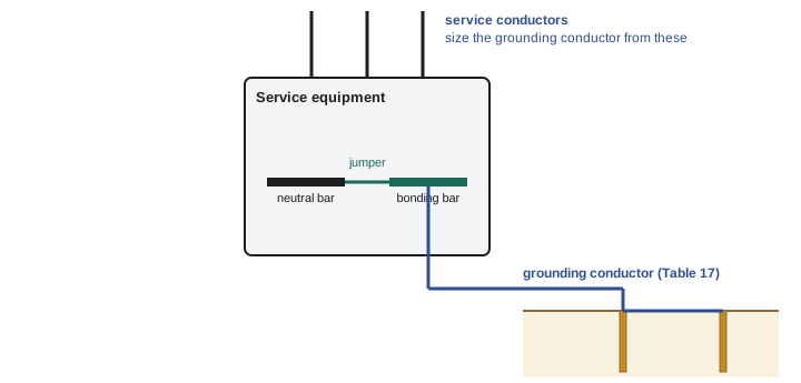
The grounding conductor is the link between the electrical system and its grounding electrode. At a typical service, it runs from the grounded conductor terminal or grounding terminal in the service equipment to the rods, plate or footing electrode outside. It does not carry current in normal operation, and it carries very little during an ordinary fault inside the building, because fault current returns along the bonding path. What it must survive is the occasional large current from a lightning strike, a surge or a fault on the utility system, and it must last for the life of the building without breaking, corroding or coming loose.
Sizing the grounding conductor is one of the most common lookup questions on master exams, and one of the easiest to get wrong, because candidates reach for the wrong table or size the conductor from the wrong quantity. This lesson explains the logic behind the Code's approach, walks through the minimum size rule and the role of Table 17, and covers the installation requirements that come with them.
Table 17 values are not reproduced here. The worked examples use an invented practice table with made-up size codes, so that you learn the method without memorizing numbers that might differ from the real table. Look up the real values in your own 2024 CE Code Part I.
Bonding conductor or grounding conductor?
Denise starts by writing two questions on the board. First: which table sizes the conductor from a service's grounded conductor terminal to the ground rods? Second: which table sizes the bare conductor inside a cable feeding a sub-panel? Marcus answers Table 16 for both, then catches himself. The first is a grounding conductor, sized from Table 17. The second is a bonding conductor, sized from Table 16. The two tables look similar, and they are sized from different things, and mixing them up is the single most common grounding error on exams.
Remember the logic from lesson 1. A bonding conductor carries fault current from a circuit back to the source, so its size follows the overcurrent device that has to clear that fault. A grounding conductor connects the system to earth, so its size follows the size of the system itself, which is represented by the service conductors. That is why Table 17 is entered with the ampacity of the largest service conductor and Table 16 is entered with the rating of the overcurrent device or, at the service, the ampacity of the largest ungrounded conductor.
The minimum size
The Code sets an absolute minimum size for a grounding conductor: subrule 10-114(1) requires at least No. 6 AWG copper or No. 4 AWG aluminum. However small the service, the grounding conductor cannot be smaller than that. The minimum exists for mechanical strength as much as electrical capacity: a grounding conductor runs along foundations and through soil, where a smaller conductor would be easily damaged.
For larger systems, the size goes up according to Table 17, which relates the ampacity of the largest service conductor, or the equivalent for parallel conductors, to the minimum grounding conductor size for copper and for aluminum. Read the notes under the table and the rule that refers to it carefully: they explain how to treat parallel service conductors and when a larger conductor is or is not required.
Using the practice table
The table below has the same shape as Table 17 but uses invented size codes, G1 to G6, instead of real conductor sizes. G1 stands for the minimum size. Use it to practise the method; on the exam, use the real table.
| Ampacity of largest service conductor (or equivalent) | Practice grounding conductor size (copper) | Practice grounding conductor size (aluminum) |
|---|---|---|
| Up to 165 A | G1 | G2 |
| 166 to 200 A | G2 | G3 |
| 201 to 260 A | G3 | G4 |
| 261 to 355 A | G4 | G5 |
| 356 to 475 A | G5 | G6 |
| Over 475 A | G6 | G6+ |
Worked problem
The Aspen Ridge service
The Aspen Ridge bungalow, after the basement suite was added in MELC-102, has a 400 A service with service conductors whose ampacity is 400 A. Using practice table P-17, find the copper grounding conductor size code.
Show solution
- The quantity to look up is the ampacity of the largest service conductor: 400 A.
- 400 A falls in the band 356 to 475 A.
- The practice size is G5 for copper. On the exam, you would read the real size from Table 17 and check it is not less than the minimum in 10-114(1).
Answer: Practice size G5 (copper).
Here is the mistake Denise hopes to catch. Some candidates look up the main breaker rating instead of the conductor ampacity. For a straightforward service, the two are often close, but not always: a service with conductors larger than the minimum, perhaps oversized for voltage drop, has a conductor ampacity higher than its breaker. Table 17 is entered with the conductor ampacity.
Parallel service conductors
Larger services often use several sets of conductors in parallel, because single conductors large enough to carry the whole current are hard to handle and terminate. For grounding conductor sizing, the Code treats parallel conductors by their equivalent: the combined size or ampacity of the conductors in parallel for one phase. The method is described in the rule and table notes; the common approach is to add the cross-sectional areas of the parallel conductors and treat the sum as one conductor.
Worked problem
The Riverbend Condos service
Riverbend Condos has an 800 A service supplied by three parallel sets of 350 kcmil copper conductors per phase. Find the equivalent area for grounding conductor sizing, then explain how you would use it.
Show solution
- Equivalent area = 3 × 350 kcmil = 1050 kcmil.
- Find the ampacity that corresponds to a single conductor of that equivalent size, or use the parallel-conductor method in the table notes, as your code book describes.
- Enter Table 17 with that equivalent, and read the grounding conductor size for copper or aluminum.
Answer: Equivalent of 1050 kcmil per phase, used to enter Table 17.
def equivalent_kcmil(sets, kcmil_each):
    return sets * kcmil_each

AWG_KCMIL = {'1/0': 105.6, '2/0': 133.1, '3/0': 167.8, '4/0': 211.6}

services = [
    ('Riverbend Condos', 3, 350),
    ('Small plaza', 2, 250),
    ('Farm main', 2, AWG_KCMIL['4/0']),
]
for name, sets, each in services:
print(f'{name:18s} {sets} x {each:6.1f} kcmil = {equivalent_kcmil(sets, each):7.1f} kcmil equivalent')Riverbend Condos 3 x 350.0 kcmil = 1050.0 kcmil equivalent Small plaza 2 x 250.0 kcmil = 500.0 kcmil equivalent Farm main 2 x 211.6 kcmil = 423.2 kcmil equivalent
Edit the services list with your own examples. The point of the exercise is to make the equivalence automatic: on the exam, you will be given parallel conductors and expected to find the equivalent before going to the table.
Materials
Grounding conductors are usually copper, either bare or insulated. Aluminum is permitted under conditions, because aluminum corrodes in contact with earth, concrete and masonry. Read the material rule for grounding conductors to see where aluminum may and may not be used, and what protection it needs. Copper-clad aluminum and other materials appear in some rules for specific applications. On an exam, if a question proposes aluminum in direct contact with soil, it is almost certainly testing whether you know the restriction.
Installation
The installation rules for grounding conductors are as important as the size, and they produce some of the most frequent inspection deficiencies. The requirements, paraphrased, include:
- Continuity. The grounding conductor should run without a splice or joint, except where the Code permits a joining method, such as an irreversible compression connector or an exothermic weld, or a connection to a busbar.
- Protection. Where it is exposed to mechanical damage, the grounding conductor must be protected, for example in conduit or by running it along a protected route. Smaller grounding conductors have stricter protection requirements than larger ones.
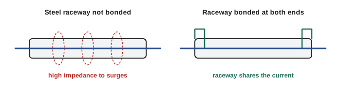
- Metal enclosures. Where a grounding conductor is run in a metal raceway or enclosure, the raceway affects the conductor's impedance to surges, and the Code has requirements for bonding the raceway to the conductor so the two act together.
- Connection to the electrode. The connection must use a method approved for the purpose and location, as lesson 4 described, and be accessible where the rules require.
The third point needs explanation, because exam questions test it. A steel conduit around a single conductor acts like the core of an inductor. For a fast-rising lightning or surge current, the steel's magnetic effect greatly increases the impedance of the conductor inside it, so that the surge would rather flash over somewhere else than travel down the grounding conductor. Bonding the conduit to the conductor at both ends lets the conduit carry the current in parallel and removes the choke effect. That is the physical reason behind the Code's requirement.
Grounding conductors for separately derived systems
When a transformer or generator creates a new system inside a building, that system needs its own connection to ground: a grounding conductor from the system bonding point to a suitable electrode, often the building steel, a metal water pipe where permitted, or the building's main electrode system. Its size is again based on the largest conductor of the derived system, using Table 17, not on the primary conductors. Lesson 9 covers separately derived systems in full.
Worked problem
The dental clinic transformer
The Gaetz Avenue dental clinic's 75 kVA, 600 to 208Y/120 V transformer has secondary conductors with an ampacity of 230 A. Using practice table P-17, find the copper grounding conductor size code for the derived system.
Show solution
- The derived system's largest conductors are the secondary conductors: 230 A.
- 230 A falls in the band 201 to 260 A.
- Practice size: G3 copper.
Answer: Practice size G3. On the exam, use the real Table 17 and the derived system's secondary conductor ampacity.
One service, two conductors
To fix the difference between the two tables in her mind, Priya works one service both ways. The Hartley Farms main service is a 200 A, 120/240 V service whose conductors have an ampacity of 200 A. A 60 A feeder runs from it to the grain-drying shop. Two conductors at that farm need sizing: the grounding conductor from the service to the electrodes, and the bonding conductor in the feeder to the shop.
The grounding conductor is sized from the service: she enters Table 17 with the 200 A ampacity of the service conductors. Using the practice table, that gives G2 for copper. The bonding conductor in the feeder is sized from the feeder's overcurrent device: she enters Table 16 with the 60 A rating of the feeder breaker. The two conductors are different sizes for different reasons, and neither can be found from the other's table. When Denise asks what would change if the farm later replaced the 60 A feeder breaker with a 100 A breaker and larger conductors, Priya answers correctly that the feeder's bonding conductor would have to be re-checked against Table 16, but the service grounding conductor would not change at all.
Marcus adds one more variation: what if the service conductors had been upsized for voltage drop to a size with a higher ampacity than the 200 A main breaker? Then Table 17 is entered with the larger ampacity, because it is the conductor that represents the size of the system. The breaker rating plays no part in the grounding conductor lookup.
Where exam questions trip candidates
Denise lists the traps she has seen most often in grounding conductor questions, and the group adds them to their lookup sheets:
- Using Table 16 for a grounding conductor, or Table 17 for a bonding conductor.
- Entering Table 17 with the main breaker rating instead of the service conductor ampacity.
- Forgetting the parallel equivalent and entering the table with one set of conductors.
- Forgetting the absolute minimum size and reading a smaller size from the table for a small service.
- Sizing a separately derived system's grounding conductor from the transformer's primary conductors.
- Proposing aluminum in contact with earth or masonry.
Priya adds one of her own: reading the copper column when the question says aluminum. Under exam pressure, she says, the eye goes to the first column every time.
Common mistakes
MistakeSizing the grounding conductor from Table 16.
InsteadGrounding conductors use Table 17; bonding conductors use Table 16.
MistakeEntering Table 17 with the main breaker rating.
InsteadEnter it with the ampacity of the largest service conductor, or the equivalent for parallel sets.
MistakeIgnoring parallel sets.
InsteadUse the equivalent of all the parallel conductors for one phase, as the table notes describe.
MistakeChoosing a grounding conductor smaller than the minimum.
InsteadNever go below the minimum in 10-114(1), No. 6 copper or No. 4 aluminum.
MistakeRunning a grounding conductor through steel conduit without bonding the conduit.
InsteadBond the raceway to the conductor so it cannot act as a choke to surges.
Summary and key terms
- A grounding conductor connects the system to the electrode and carries little current except during surges and utility faults.
- Its size follows the system, entered as the ampacity of the largest service conductor in Table 17.
- Subrule 10-114(1) sets an absolute minimum of No. 6 AWG copper or No. 4 AWG aluminum.
- Parallel service conductors are treated by their equivalent for one phase.
- Installation rules cover continuity, protection, metal raceways, materials and the electrode connection.
- Table 17
- The Code table giving the minimum size of grounding conductor for an AC system, based on the largest service conductor.
- Equivalent conductor
- The combined size of parallel conductors for one phase, used for table lookups.
- Choke effect
- The increase in surge impedance of a conductor enclosed alone in a steel raceway.
- Exothermic weld
- A permanent connection made by a chemical reaction that fuses the conductors.
- Minimum size rule
- The rule setting the smallest grounding conductor permitted regardless of system size.
Practice problems
Work each problem on paper first, then reveal the answer to check.
A service has two parallel sets of 500 kcmil copper per phase. What equivalent do you use?
Show answer
1000 kcmil.
Which table sizes the bonding conductor in a feeder to a sub-panel?
Show answer
Table 16, based on the feeder's overcurrent device.
Using practice table P-17, size a copper grounding conductor for a service with 175 A conductors.
Show answer
Band 166 to 200 A: G2.
Why must a steel conduit around a grounding conductor be bonded to it?
Show answer
To prevent the conduit acting as a choke to surge current.
Lesson quiz · 5 questions
Score 60% or more to complete this lesson.
Create a free account to save your progress, take quizzes and earn a certificate.