
MELC-104 · Lesson 11 of 12 · 22 min
Common grounding and bonding errors
▶ Video coming soon A video version of this lesson is on the way.
Denise Lafleur spent twenty-two years as an electrical safety codes officer, and she kept a notebook. Every deficiency she wrote up went into it, and by the time she retired she could tell you which mistakes she saw every week, which every month, and which only once in a career. Grounding and bonding errors filled more pages than any other topic. Some were simple oversights. Some came from habits learned under older codes. Some came from a misunderstanding of what grounding and bonding are for, the misunderstanding lesson 1 was written to prevent.
This lesson is built from that notebook. It collects the errors that inspectors find most often, explains why each one matters by tracing what happens during a fault or in normal operation, and connects each to the part of Section 10 that addresses it. Exam writers draw on the same list. A question that describes an installation and asks what is wrong with it is usually testing one of these errors.
As throughout the course, the Code requirements are paraphrased. Look up each rule mentioned in your own 2024 CE Code Part I.
Error 1: the neutral bonded at a sub-panel
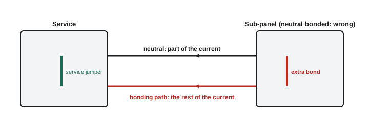
The most common grounding error, by a wide margin, is a neutral bonded to its enclosure somewhere downstream of the service: a sub-panel with the bonding screw left in, a feeder to a separate building wired as a miniature service, a generator with its factory neutral bond left in place behind a solid-neutral transfer switch. Each creates a second neutral-to-bonding connection in the same system.
With two connections, normal neutral current divides between the neutral conductor and every parallel metal path between the two points: the feeder's bonding conductor, metal raceways, cable armour, water piping, building steel. Those paths carry current continuously, which corrodes joints, heats connections, creates magnetic fields that disturb sensitive equipment and, on large services with ground fault protection, causes nuisance trips because the protection sees the neutral current on the bonding path as a fault.
Worked problem
Objectionable current at the dental clinic
At Gaetz Avenue, a sub-panel on the 208Y/120 V system was installed with its bonding screw left in, so its neutral is bonded to its enclosure. The feeder neutral has a resistance of 0.05 Ω, and the parallel path through the feeder's EMT and bonding conductor back to the transformer's bonding point is 0.08 Ω. The sub-panel's neutral current is 40 A. How does it divide?
Show solution
- The two paths are in parallel between the sub-panel and the transformer: 0.05 × 0.08 / (0.05 + 0.08) ≈ 0.0308 Ω.
- Voltage across the paths ≈ 40 × 0.0308 ≈ 1.23 V.
- Neutral conductor current ≈ 1.23 / 0.05 ≈ 24.6 A; bonding path current ≈ 1.23 / 0.08 ≈ 15.4 A.
- More than a third of the normal neutral current is flowing on the raceway and bonding conductor, continuously.
Answer: About 24.6 A on the neutral and 15.4 A on the bonding path.
The fix is to remove the extra bond, so that the neutral is isolated at the sub-panel and the bonding conductor lands on a separate bonding bar. Section 10's rule against connecting the grounded conductor to the bonding system on the load side of the service or source is the rule this error breaks.
Error 2: the missing system bonding jumper
The opposite mistake is less common but more dangerous: no system bonding jumper at all, so the neutral and the bonding system are never connected. It happens when a panel is installed as a sub-panel but used as the service, when a separately derived transformer is installed without its jumper, or when someone removes a jumper chasing a noise problem. With no connection, a fault to a bonded enclosure has no low-impedance path back to the source neutral. The fault current has to return through the earth, and as lesson 1 showed, that limits it to a few amperes. The breaker does not trip, and every bonded surface in the system rises toward the full phase-to-neutral voltage.
Worked problem
No jumper at the transformer
A new 208Y/120 V transformer was installed with no system bonding jumper. A 120 V fault occurs to a bonded enclosure, and the only return path is through the building steel, the earth and the service electrode, totalling 12 Ω, plus 0.2 Ω of wiring. Find the fault current and comment.
Show solution
- I = 120 / (12 + 0.2) ≈ 9.8 A.
- A 20 A breaker protecting the circuit never trips.
- Every bonded enclosure on the derived system sits at a dangerous voltage until the fault is found.
Answer: About 9.8 A, so the fault persists.
Error 3: a ground rod instead of a bonding conductor
Lesson 1 started with this one, and it never goes away: a separate ground rod at a piece of equipment, a pump, a sign or an outbuilding, used instead of a bonding conductor run with the circuit. The rod may make the equipment feel grounded, but it cannot carry enough current to operate the overcurrent device. Supplementary electrodes are sometimes permitted in addition to the bonding conductor; they are never permitted instead of it.
Error 4: sizing from the wrong table or the wrong quantity
Paper errors cause real problems too. Inspectors regularly find bonding conductors sized from the load rather than the overcurrent device, bonding conductors in parallel runs divided among the raceways, and grounding conductors sized from Table 16. Each one produces a conductor that may be too small for its duty. Lessons 5 and 6 cover the correct methods; this error belongs in the lesson because candidates under exam pressure make exactly these mistakes.
| Conductor | Correct table | Correct entry quantity |
|---|---|---|
| Service grounding conductor | Table 17 | Ampacity of largest service conductor (or equivalent for parallel sets) |
| Bonding conductor at the service | Table 16 | Ampacity of largest ungrounded service conductor |
| Bonding conductor for a feeder or branch circuit | Table 16 | Rating or setting of the overcurrent device |
| Each bonding conductor in a parallel run | Table 16 | Overcurrent device protecting the whole feeder |
| Field-installed system bonding jumper for a derived system | Table 16 | Quantity stated in the rule, usually largest derived-system conductor |
| Grounding conductor for a derived system | Table 17 | Largest conductor of the derived system |
Error 5: poor bonding joints
Many bonding failures are mechanical: locknuts on concentric knockout rings at the service, lugs fastened over paint, sheet-metal screws used as bonding terminals, loose EMT set-screw fittings, missing bonding jumpers across expansion fittings, flexible metal conduit used as the bonding path beyond the Code's limits. Each one adds resistance to the fault path or makes it likely to fail under fault current. Lessons 7 and 8 cover the methods. Denise's notebook has one entry she underlined three times: a service raceway bonded only by a standard locknut over concentric rings, in a building with a large available fault current. The rings would have burned open in the first serious fault.
Error 6: isolated grounds run to a separate rod
Isolated-ground receptacles are meant to reduce electrical noise by giving sensitive equipment a bonding path that does not share the raceway. Some installers misunderstand the idea and run the isolated bonding conductor to a dedicated ground rod, sometimes called a clean ground. That removes the equipment's fault path entirely, because the rod is not connected to the source neutral by a low-impedance path, and it can create dangerous voltage differences between the isolated equipment and everything else in the room during a surge or fault. The isolated bonding conductor must run back, continuous and insulated, to the panel or service as lesson 7 described.
Error 7: electrodes not interconnected
A building with a power electrode, a separate communication electrode and a lightning protection electrode, none of them bonded together, is a building waiting for a surge to destroy any equipment connected to two systems. Lesson 4 showed how a voltage difference of thousands of volts can appear between unbonded electrodes during a nearby strike. The fix is the interconnection the Code requires.
Error 8: piping and metal left unbonded
Renovations break bonding paths all the time. A plastic section spliced into copper water piping, a water meter replaced without a jumper, a gas line extended with corrugated tubing and no bond, a new metal structure added to a building and never connected. Each leaves metal that people touch with no guarantee of being at the same potential as everything else. The inspector's question is always the same: if a fault reached this metal, where would the current go?
Error 9: aluminum and corrosion
Grounding and bonding connections have to last decades, often outdoors, underground or in damp locations. Aluminum grounding conductors in contact with earth or masonry, copper and aluminum joined without a suitable connector, steel clamps on copper-clad rods in wet soil, and connectors not approved for direct burial all corrode. A grounding conductor that has corroded through at its electrode clamp has disconnected the system from earth without anybody knowing. Material and connector rules exist for this reason.
Error 10: ungrounded systems with ignored detection
On industrial sites, ungrounded and high-resistance grounded systems keep running after a first ground fault, and their detection systems tell the operators where the fault is. The error is not in the installation but in the response: a ground detection lamp that has shown a fault for months, or an alarm that has been silenced. The system is now one fault away from a phase-to-phase failure. Exam questions on lesson 3's material sometimes describe this situation and ask what it means.
Error 11: a grounding conductor choked by steel
A grounding conductor run alone through a steel conduit or sleeve, with the steel not bonded to it at both ends, looks tidy and protected. To a fast-rising surge, it is a coil with an iron core. Lesson 5 explained the choke effect: the steel raises the conductor's impedance to surge current so much that a lightning surge may flash over to nearby metal instead of following the conductor to the electrode. Inspectors find this most often where a contractor sleeved the grounding conductor through a foundation wall or ran it in EMT down the outside of a building for protection. The fix is to bond the raceway to the conductor at both ends, or to use a non-metallic sleeve where protection is all that is needed.
Error 12: the neutral used as a bonding conductor
Older installations, and some older appliance wiring practices, used the neutral to bond the frames of ranges and dryers, through a strap inside the appliance. Some installers still connect an appliance or equipment frame to the neutral out of habit, or use the neutral as the bonding conductor for a new circuit where the cable has no separate bonding conductor. On the load side of the service, that is another neutral-to-bonding connection, with all the problems of error 1, plus a specific hazard: if the neutral opens, the equipment frame rises to the phase voltage through the load. When an old appliance is reconnected with a new four-conductor cord and circuit, the frame-to-neutral strap must be removed according to the manufacturer's instructions, so that the frame is bonded only through the bonding conductor.
Denise's inspection walk
Denise gives the group the walk she used on every commercial inspection, in the order she did it:
- At the service: one system bonding jumper, correctly sized; grounding conductor sized from Table 17 and properly connected to the electrode; service raceways bonded with approved methods.
- At the electrodes: correct type and installation, interconnected with any communication or lightning electrodes, connectors approved for the location.
- At each sub-panel: neutral isolated, separate bonding bar, bonding conductor sized from the feeder's overcurrent device.
- At each transformer or generator: separately derived or not, and one system bonding jumper where it should be.
- Along the raceways: fittings tight, jumpers where required, flexible sections within limits, bonding conductors in non-metallic raceways.
- At the piping and metal: water and gas bonded, jumpers around meters, isolated sections bonded.
Priya copies the list into her lookup sheet. Marcus says it doubles as a design checklist, because if a design passes Denise's walk, it will pass an inspection.
checks = [
    ('Single system bonding jumper at the service', True),
    ('Grounding conductor sized from Table 17', True),
    ('Neutral isolated at every sub-panel', False),
    ('Electrodes interconnected', True),
    ('Bonding jumper around the water meter', False),
    ('Isolated-ground conductor returns to the panel', True),
]
failed = [name for name, ok in checks if not ok]
print(f'{len(checks) - len(failed)} of {len(checks)} checks passed')
for name in failed:
print(' deficiency:', name)4 of 6 checks passed deficiency: Neutral isolated at every sub-panel deficiency: Bonding jumper around the water meter
Edit the list as you walk your own jobs. The point is not the script but the habit: a fixed sequence, checked the same way every time.
Common mistakes
MistakeLeaving the bonding screw in a sub-panel.
InsteadRemove it; isolate the neutral and use a separate bonding bar.
MistakeRemoving a system bonding jumper to cure electrical noise.
InsteadNever remove the only neutral-to-bonding connection; find the real cause of the noise.
MistakeRunning an isolated-ground conductor to a dedicated rod.
InsteadRun it back to the panel or service, continuous and insulated.
MistakeDividing a bonding conductor among parallel runs.
InsteadSize each run's bonding conductor from the whole feeder's overcurrent device.
MistakeIgnoring a ground detection alarm on an ungrounded system.
InsteadFind and fix the first fault before a second one causes a phase-to-phase failure.
Summary and key terms
- A second neutral-to-bonding connection downstream of the service puts normal current on bonding paths.
- A missing system bonding jumper forces fault current through the earth, so faults persist.
- Rods never replace bonding conductors, and isolated grounds still return to the panel.
- Most sizing errors come from using the wrong table or the wrong entry quantity.
- Poor joints, unbonded piping, unconnected electrodes and corrosion defeat otherwise good designs.
- Objectionable current
- Normal current flowing on bonding paths because of an improper neutral-to-bonding connection.
- Clean ground
- An informal, and misleading, name for a separate electrode used for sensitive equipment.
- Bonding screw
- The removable screw or strap in a panel that bonds the neutral bar to the enclosure.
- Deficiency
- An inspector's finding that an installation does not meet the Code.
- Parallel path
- Any metal route that carries current alongside the conductor intended to carry it.
Practice problems
Work each problem on paper first, then reveal the answer to check.
A sub-panel neutral of 0.06 Ω is bonded at the panel, with a parallel bonding path of 0.06 Ω. How does 30 A of neutral current divide?
Show answer
Equally: 15 A on each.
A derived system has no system bonding jumper; a 120 V fault returns through 15 Ω of earth path. Find the current.
Show answer
About 8 A; the breaker does not trip.
What table sizes the grounding conductor for a separately derived system?
Show answer
Table 17, using the derived system's largest conductor.
Name two causes of objectionable current.
Show answer
A bonded neutral at a sub-panel; a generator neutral bonded behind a solid-neutral transfer switch.
Lesson quiz · 5 questions
Score 60% or more to complete this lesson.
Create a free account to save your progress, take quizzes and earn a certificate.