
MELC-103 · Lesson 8 of 12 · 22 min
Breakers, fuses and coordination
▶ Video coming soon A video version of this lesson is on the way.
Lesson 7 set out what overcurrent protection must do. This lesson looks at the devices that do it, circuit breakers and fuses, and at how devices in series work together. A master electrician is expected to choose between breakers and fuses, read their ratings, understand current limitation and series ratings, and know when the Code requires devices to be selectively coordinated so that a fault opens only the device closest to it. These topics bridge the Code and the manufacturer's data, and exam questions often give you a piece of manufacturer information and ask you to apply a Code rule to it.
All curve shapes, ratios and multiples in this lesson are illustrative. Real coordination studies use the manufacturer's published time-current curves and selectivity tables, and the Code rules that require coordination are in specific sections. Read them in your 2024 copy.
How a circuit breaker works
A thermal-magnetic circuit breaker has two tripping elements. The thermal element is a bimetal strip that bends as it heats with current; under a sustained overload it bends far enough to release the latch and open the breaker. Because heating takes time, the thermal element responds slowly to moderate overloads and ignores short surges such as motor starting current. The magnetic element is a coil that acts almost instantly when current exceeds a set multiple of the rating, typically during a short circuit. Together they produce the two-part time-current curve from Lesson 7: a sloping overload region and a near-vertical instantaneous region.
Larger breakers often have electronic trip units instead of, or in addition to, thermal-magnetic elements. These measure current electronically and let the user adjust the long-time pickup, the short-time pickup and delay, the instantaneous pickup, and sometimes ground fault settings. Adjustability makes electronic breakers valuable for coordination, because their curves can be shaped to fit between upstream and downstream devices. On the exam, questions about adjustable trips usually test that the long-time setting effectively becomes the device's rating for the purposes of conductor protection.
Worked problem
Instantaneous pickup current
The 100 A feeder breaker for the Hartley Farms shop has an illustrative instantaneous pickup setting of 10 times its rating. Above what current will it trip instantaneously? Would a motor starting inrush of 650 A on the feeder trip it instantly?
Show solution
- Multiply the rating by the setting: 100 x 10 = 1000 A.
- The breaker trips instantaneously above about 1000 A.
- The motor inrush of 650 A is below 1000 A, so it falls in the thermal (time-delayed) region.
- The thermal element tolerates the short inrush, so the breaker should not trip during normal starting.
Answer: Instantaneous trip above about 1000 A; a 650 A inrush does not trip it instantly.
How a fuse works
A fuse contains a metal element that melts when current exceeds its rating for long enough. Simple fuses have one element; time-delay fuses have a slow-melting section for overloads and a fast-melting section for short circuits, which gives them a curve that tolerates motor starting while still clearing faults quickly. Fuses are single-use: once a fuse opens, it must be replaced, which some see as a drawback and others as a safety advantage because it forces someone to look for the cause.
Modern high-capacity fuses are current-limiting. When a large fault occurs, they melt so fast, within the first half-cycle of the alternating current, that the fault current never reaches its full prospective value. That limits the energy let through to the circuit downstream, reducing damage and arc flash hazard. Fuses are classified by their dimensions, interrupting ratings and current-limiting performance, with classes such as J, L, RK1, RK5 and CC in common use. The class affects which fuse holder accepts the fuse, so that a fuse with a lower interrupting rating cannot be substituted by mistake. Read the manufacturer's data and the Code's rules on fuse holders and rejection features when a question involves replacing or substituting fuses.
| Feature | Breakers | Fuses |
|---|---|---|
| After a fault | Reset (after finding the cause) | Replace the fuse |
| Overload response | Thermal or electronic long-time element | Slow-melting element (time-delay types) |
| Short-circuit response | Magnetic or electronic instantaneous element | Fast-melting element, often current-limiting |
| Adjustability | Possible with electronic trip units | Change the fuse rating or class |
| Interrupting ratings | Commonly 10 kA to 65 kA and up | Often very high, such as 200 kA, for current-limiting classes |
| Coordination tools | Curves and manufacturer selectivity tables | Published selectivity ratios between fuse classes |
Series ratings
Sometimes a downstream breaker has an interrupting rating lower than the available fault current at its location. That is normally a violation of Rule 14-012. Manufacturers can test certain combinations of an upstream device and a downstream breaker together, so that the pair safely interrupts a higher fault current than the downstream breaker could alone. These tested combinations are called series ratings, and the Code allows them only where the combination is tested and marked as such, the equipment is labelled, and certain other conditions are met. A series-rated combination cannot be assembled on site by choosing two devices that seem compatible.
Marcus asks whether the Hartley Farms shop panel could use cheaper 10 kA branch breakers if the upstream feeder breaker is rated 22 kA. Denise's answer is that it depends entirely on whether the manufacturer has tested and listed that exact combination, and whether the panel is marked for it. Without that, every breaker must have its own interrupting rating at least equal to the available fault current at the panel. On the exam, a series rating question usually turns on whether the combination is tested and marked.
Selective coordination
Devices in series form a chain: main breaker, feeder breaker, branch breaker. When a fault occurs on a branch circuit, the ideal outcome is that only the branch breaker opens, leaving the feeder and main closed so that the rest of the building stays powered. This is selective coordination, sometimes called selectivity. It is achieved by choosing devices whose time-current curves do not overlap for any current up to the available fault current at the downstream device: the downstream device always opens first.
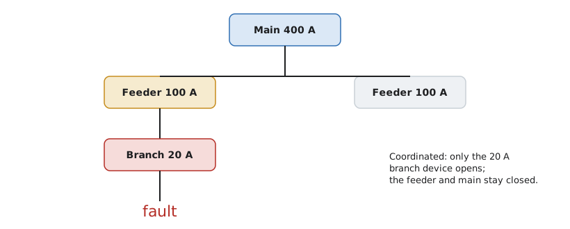
Coordination is good practice everywhere, but the Code requires it only in specific systems where an outage of the whole building would be dangerous: typically emergency systems, fire pumps and certain health care and life safety systems. Find the rules requiring coordination in the sections for those systems in your copy, and note the wording, because some rules require coordination for all fault currents and others for a defined range of times. On the exam, you may be asked whether coordination is required for a given system, or whether a given pair of devices is coordinated based on information provided.
For fuses, manufacturers publish selectivity ratios: if the upstream fuse rating is at least a certain multiple of the downstream fuse rating, and both are of compatible classes, the pair is selective. For breakers, manufacturers publish selectivity tables listing pairs that are selective up to a stated fault current. Neither of these is in the Code; they are manufacturer data that the Code relies on. Exam questions give you the ratio or table and ask you to apply it.
Worked problem
Checking a fuse selectivity ratio
At the Hartley Farms bin yard, a 200 A time-delay fuse protects the feeder, and 60 A fuses of a compatible class protect each bin fan. The manufacturer states an illustrative selectivity ratio of 2:1 for this pair of classes. Are the fuses selective? Would they be if the feeder fuse were 100 A?
Show solution
- Divide the upstream rating by the downstream rating: 200 / 60 = 3.33.
- Compare with the required ratio: 3.33 is at least 2, so the pair is selective.
- With a 100 A feeder fuse: 100 / 60 = 1.67, which is less than 2.
- The 100 A and 60 A pair would not be selective under the stated ratio.
Answer: Selective at 200 A to 60 A; not selective at 100 A to 60 A, with the illustrative 2:1 ratio.
def selective(upstream, downstream, ratio):
    return upstream / downstream >= ratio

pairs = [(200, 60), (100, 60), (400, 200), (400, 225)]
for up, down in pairs:
print(f'{up} A over {down} A at 2:1 ->', 'selective' if selective(up, down, 2.0) else 'not selective')200 A over 60 A at 2:1 -> selective 100 A over 60 A at 2:1 -> not selective 400 A over 200 A at 2:1 -> selective 400 A over 225 A at 2:1 -> not selective
The script makes a point that is easy to miss: 400 A over 200 A is exactly 2:1 and passes, but 400 A over 225 A falls just short. When a question gives you ratings close to the ratio, do the division rather than estimating.
Continuous-duty ratings
Most breakers and fuse assemblies are tested and rated for loads that do not run at their full rating continuously. That is why Rule 8-104 limits continuous loads to a fraction of the rating unless the equipment is marked for continuous operation at its full rating. Some larger breakers and switches are tested and marked for continuous operation at full rating, which lets a designer use the whole rating for continuous loads, provided the conductors and the enclosure ventilation also allow it. On the exam, look for the marking in the scenario: if equipment is described as marked for continuous operation at full rating, a different Rule 8-104 limit applies than if it is not.
Priya notices that the questions she misses on this topic are always ones where she assumed the standard limit without checking whether the scenario mentioned the marking. She adds a line to her checklist: for any continuous load, ask whether the device and assembly are marked for full-rating continuous duty.
Protective devices and arc flash
Protective devices also shape the arc flash hazard that workers face when they open energized equipment. The energy released in an arc flash depends on the fault current and on how long it flows, and the clearing time comes from the time-current curve of the upstream device. A device that clears a fault in a few cycles produces a much smaller arc flash than one that takes half a second. That is why current-limiting fuses and breakers with fast instantaneous settings can reduce the arc flash category of downstream equipment, and why some electronic trip units have a maintenance mode that temporarily lowers the instantaneous pickup while work is under way.
There is a tension here with coordination. Coordination often calls for delaying upstream devices so that downstream devices clear first, and those delays increase the arc flash energy at the upstream equipment. Engineers balance the two with careful settings, zone-selective interlocking and maintenance switches. A master electrician does not usually carry out the study, but must understand why settings matter and must not change them casually. CSA Z462, the workplace electrical safety standard covered in MELC-106, governs how arc flash risk is assessed and controlled.
Denise tells a story from an industrial plant where an electrician raised the instantaneous setting on a feeder breaker to stop nuisance trips. The trips stopped, but the arc flash label on the downstream switchgear was now wrong, because the clearing time had grown. When a worker later opened that gear wearing the protective equipment specified on the label, he was underprotected. The lesson for the exam and for the field is the same: protective device settings are part of the safety design, and changing them changes the hazard.
Choosing devices at Hartley Farms
The group's final choices for Hartley Farms show the principles at work. The 400 A service uses a breaker with an electronic trip unit so that its settings can be coordinated with the feeders. The motor control centre uses fused disconnects with time-delay fuses for the dryer and auger motors, chosen for their tolerance of starting current and their current-limiting performance. The office and shop panels use standard thermal-magnetic branch breakers with an interrupting rating checked against the fault current calculated in Lesson 7. No series ratings are relied on. The bin yard fan fuses are selected with the manufacturer's selectivity ratio so that a fault on one fan does not shut down the whole yard during harvest.
Common mistakes
MistakeBuilding a series rating from devices that seem compatible.
InsteadSeries ratings must be tested and marked combinations.
MistakeAssuming coordination is required everywhere.
InsteadThe Code requires it in specific systems such as emergency and fire pump systems; elsewhere it is good practice.
MistakeEstimating a selectivity ratio instead of dividing.
InsteadDivide the ratings; pairs close to the ratio often fail by a small margin.
MistakeReplacing a fuse with any fuse that fits the clips.
InsteadUse the correct class and rating; rejection features prevent unsafe substitutions.
MistakeUsing the full rating for continuous loads on standard equipment.
InsteadOnly equipment marked for full-rating continuous duty may be loaded that way.
Summary and key terms
- Thermal-magnetic breakers have a slow thermal element for overloads and a fast magnetic element for faults.
- Time-delay fuses tolerate motor starting; current-limiting fuses cut fault energy within half a cycle.
- Series ratings are allowed only for tested, marked combinations.
- Selective coordination makes only the device nearest a fault open; the Code requires it in certain systems.
- Manufacturer selectivity ratios and tables, not the Code, tell you whether a pair coordinates.
- Thermal element
- The part of a breaker that trips on sustained overload as it heats.
- Magnetic element
- The part of a breaker that trips almost instantly on high fault current.
- Current-limiting fuse
- A fuse that clears a large fault before the current reaches its full prospective value.
- Series rating
- A tested and marked combination of devices that together interrupt a higher fault current.
- Selective coordination
- Arrangement of devices so that only the device nearest a fault opens.
Practice problems
Work each problem on paper first, then reveal the answer to check.
A 60 A breaker has an instantaneous pickup of 8 times its rating. Above what current does it trip instantly?
Show answer
60 x 8 = 480 A.
Is a 400 A fuse over a 200 A fuse selective at a 2:1 ratio?
Show answer
Yes; 400 / 200 = 2, which meets the ratio.
Is a 150 A fuse over an 80 A fuse selective at a 2:1 ratio?
Show answer
No; 150 / 80 = 1.875, less than 2.
May an electrician assemble a series-rated combination on site from two compatible devices?
Show answer
No; only tested and marked combinations are permitted.
Name a system where the Code requires selective coordination.
Show answer
Emergency systems or fire pumps, among others named in the relevant sections.
Lesson quiz · 5 questions
Score 60% or more to complete this lesson.
Create a free account to save your progress, take quizzes and earn a certificate.