
MELC-103 · Lesson 7 of 12 · 22 min
Overcurrent protection principles in Section 14
▶ Video coming soon A video version of this lesson is on the way.
Section 14 of the CE Code governs protective and control devices: fuses, circuit breakers, ground fault and arc fault protection, and the switches and controllers that open circuits. Its central idea is simple. Every ungrounded conductor must be protected against current higher than it can safely carry, by a device that opens the circuit before the conductor or the equipment it supplies is damaged. Applying that idea correctly requires three things: knowing what kind of overcurrent you are protecting against, choosing a device with the right rating and characteristics, and putting it in the right place.
This lesson covers the principles: overload and short circuit, the rating of overcurrent devices in relation to conductor ampacity, interrupting ratings and available fault current, and where devices must be located. The next lesson covers breakers, fuses and coordination, and Lesson 9 covers ground fault and arc fault protection. Rule numbers are pointers; read every rule in your 2024 copy, including its subrules.
Overload and short circuit
Overcurrent is any current above the rating of a conductor or piece of equipment. It comes in two forms that behave very differently. An overload is a moderate excess current flowing in the normal circuit path: a motor straining against a jammed auger, too many heaters on one circuit, a feeder supplying more load than it was designed for. Overloads heat conductors slowly, over minutes or hours. A short circuit or fault is a very large current flowing through an abnormal path, such as a phase conductor touching another phase or a grounded enclosure. Fault currents can be hundreds or thousands of times the normal current and can do damage in a fraction of a second.
Protective devices are designed to deal with both. For overloads, they respond slowly enough to ignore harmless short surges, such as motor starting current, but fast enough to stop the conductor overheating. For short circuits, they respond almost instantly. The time-current curve of a device shows this behaviour: on a graph of time against current, the curve slopes steeply downward, so that higher currents open the device faster.
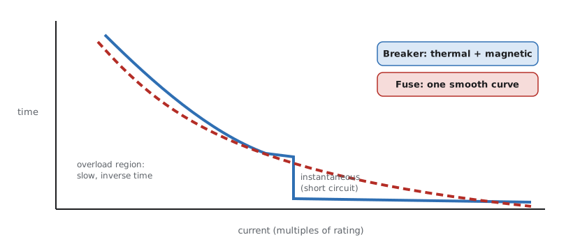
Every ungrounded conductor must be protected
The general rule in Section 14 (Rule 14-100 and the rules around it) requires overcurrent protection in each ungrounded conductor, located at the point where the conductor receives its supply, with a rating not exceeding what the conductor's ampacity allows. The identified (neutral) conductor is generally not fused or broken separately, because opening the neutral alone could leave equipment energized while appearing dead, and could cause dangerous voltages on multi-wire circuits. Where a device opens the neutral, it must open all conductors at the same time.
The rule has exceptions for conductors where protection at the supply point would be impractical or unnecessary, such as short tap conductors that meet strict length and ampacity conditions, conductors between a generator and its first protective device, some control circuit conductors, and the secondary conductors of transformers under conditions. Tap rules in particular are a favourite exam subject. A typical question describes a small conductor tapped from a large feeder and asks whether it may be used without protection at the tap point. The answer depends on the length of the tap, its ampacity relative to the feeder protection, where it ends, and whether it is protected from damage. Find the tap conditions in Section 14 of your copy and list them on your lookup sheet.
Worked problem
Is this tap acceptable?
In the Hartley Farms electrical room, Marcus proposes tapping a short run of smaller conductors off the 400 A feeder to supply a 100 A panel for the shop lighting. The tap conductors are 2.5 m long, run in rigid conduit, have an ampacity well above 100 A, and end at a 100 A main breaker in the new panel. Using the general structure of the tap rules, what must be checked?
Show solution
- Find the tap rule in Section 14 that matches the situation (short taps ending at a single overcurrent device).
- Check the length against the rule's maximum for that kind of tap.
- Check the tap conductor ampacity against the rule's minimum, which is usually tied to the rating of the device it ends in, and sometimes to a fraction of the feeder protection.
- Check that the tap is enclosed or otherwise protected from damage, as here in rigid conduit.
- Check that it ends in a single overcurrent device of a rating not exceeding the tap ampacity, here the 100 A main.
Answer: If the length, ampacity, protection and termination conditions in your copy are all met, the tap may be installed without protection at the tap point.
Tap questions reward careful reading because the conditions are cumulative. A tap that is short enough but ends in a panel without a main breaker fails. A tap that ends in a correctly sized breaker but runs exposed through a work area fails. A tap that meets every physical condition but has too little ampacity relative to the feeder protection fails. Priya's habit is to write the conditions as a checklist in the margin of her practice sheet and tick each one against the scenario before she chooses an answer.
Denise adds a practical warning from her inspecting years. Taps are often created during renovations, when an electrician adds a subpanel near an existing feeder and assumes that a short run is automatically acceptable. It is not. The tap rules exist because an unprotected small conductor connected to a large feeder could carry a fault current far beyond its ability to survive, and only the specific combination of short length, protection and adequate ampacity makes the risk acceptable.
Rating of the overcurrent device
Rule 14-104 relates the rating of an overcurrent device to the ampacity of the conductor it protects. The general principle is that the device rating should not exceed the conductor's ampacity, so that the device opens before the conductor overheats. Because devices come in standard ratings, the rule allows the next higher standard rating in some cases where the conductor's ampacity falls between standard sizes, with limits on how high this may go. Other rules modify this principle for particular loads, especially motors, where the starting current would trip a device sized exactly to the conductor, and for certain equipment that has its own protection.
At Hartley Farms, the conductor chosen for the dryer heater in Lesson 2 had a usable ampacity just above 47.5 A with a 50 A breaker. Marcus asks whether a 60 A breaker would be acceptable to avoid nuisance trips. Denise sends him to Rule 14-104 and Rule 8-104. The answer: the breaker must suit both the conductor ampacity and the continuous-load requirement, and a 60 A breaker on a conductor whose usable ampacity is in the high 40s would leave the conductor unprotected against moderate overloads. If the breaker trips, the right response is to investigate the load, not to oversize the breaker.
| Question | Rule to read | General principle |
|---|---|---|
| May a conductor be unprotected at its supply point? | Rule 14-100 and tap rules | Only under listed conditions, such as short, protected taps |
| How large may the breaker or fuse be? | Rule 14-104 | Not above conductor ampacity, with limited allowance for the next standard size |
| Does a motor circuit follow the same rule? | Section 28 | No; motor branch circuit protection is sized for starting current |
| Must the neutral be fused? | Section 14 general rules | Generally not; if opened, all conductors open together |
| Can the device interrupt the available fault? | Rule 14-012 | Its interrupting rating must not be less than the available fault current |
Interrupting rating and available fault current
A protective device must be able to interrupt the largest fault current that could flow at the point where it is installed. If the available fault current exceeds the device's interrupting rating, the device may fail violently when it tries to open, causing an arc flash or explosion instead of clearing the fault. Rule 14-012 and related rules require equipment to have an interrupting rating not less than the available fault current at its line terminals. The same principle applies to the short-circuit current rating of panelboards, motor control centres and other assemblies.
Available fault current depends mainly on the supply transformer and the impedance of the conductors between it and the point of the fault. Close to a large utility transformer, fault currents can be tens of thousands of amperes. Far away, at the end of a long branch circuit, they are much lower. A first approximation of the fault current at a transformer's secondary terminals uses the transformer's full-load current and its impedance rating: the fault current is roughly the full-load current divided by the impedance expressed as a decimal. This ignores the utility system's own impedance, so it overestimates slightly, which is the safe direction for checking interrupting ratings.
Worked problem
Fault current at the Hartley Farms transformer
The utility will supply Hartley Farms from a 150 kVA three-phase transformer at 347/600 V with an impedance of 0.04 per unit (illustrative values). What is the approximate fault current at its secondary terminals?
Show solution
- Full-load current: 150 000 / (1.732 x 600) = 144.3 A.
- Fault current: 144.3 / 0.04 = 3608 A.
- Round for the answer: about 3600 A.
- Any service equipment connected at this point must have an interrupting or short-circuit rating of at least this value (in practice, at least the next standard rating, such as 10 kA).
- In real work, obtain the available fault current from the utility and include conductor impedance.
Answer: About 3600 A available at the transformer secondary with these illustrative values.
Priya's calculator gets one more function. It estimates the fault current at the transformer and compares it with a list of standard interrupting ratings, returning the smallest one that is adequate.
import math

def full_load(kva, volts, three_phase=True):
    va = kva * 1000
    return va / (math.sqrt(3) * volts) if three_phase else va / volts

def fault_current(kva, volts, z_pu, three_phase=True):
    return full_load(kva, volts, three_phase) / z_pu

ratings = [10_000, 14_000, 18_000, 22_000, 25_000, 35_000, 65_000]

def minimum_rating(available):
    return next(r for r in ratings if r >= available)

for kva, volts, z in [(150, 600, 0.04), (75, 208, 0.05), (1000, 600, 0.0575)]:
    f = fault_current(kva, volts, z)
print(f'{kva} kVA at {volts} V, Z {z}: about {f:,.0f} A; choose at least {minimum_rating(f):,} A')150 kVA at 600 V, Z 0.04: about 3,608 A; choose at least 10,000 A 75 kVA at 208 V, Z 0.05: about 4,164 A; choose at least 10,000 A 1000 kVA at 600 V, Z 0.0575: about 16,735 A; choose at least 18,000 A
Look at the 1000 kVA result: the fault current is close to 17 000 A, so a 10 kA or 14 kA device is not enough and the script chooses 18 kA. Larger services in commercial and industrial buildings often need devices rated 22 kA, 25 kA or higher. On the exam, a question that gives you a transformer size and impedance and asks for the minimum interrupting rating is testing exactly this calculation.
Location of overcurrent devices
Besides being at the supply end of the conductor, overcurrent devices must be readily accessible (in most cases), protected from physical damage, not located where they would be exposed to ignitable materials, and arranged so that the handle position shows whether the circuit is open or closed. Section 14 also restricts locating overcurrent devices in bathrooms and similar locations in dwellings, and over steps of a stairway, among other places. These rules interact with the working space rules of Rule 2-308 and the readily accessible definition from Section 0, which MELC-101 covered.
At Hartley Farms, the group places the main distribution panel in the electrical room, away from the dust of the dryer area, with clear working space in front. The motor starters and their overcurrent devices go in a motor control centre in the same room. The bin yard has its own small panel at the pole, with a rain-tight enclosure and protection from vehicles. Each location decision traces back to Section 14, Section 2 and the location definitions.
Common mistakes
MistakeTreating overloads and short circuits as the same thing.
InsteadOverloads are moderate and slow; faults are large and fast; devices handle both differently.
MistakeOversizing a breaker to stop nuisance trips.
InsteadInvestigate the load; the device must protect the conductor under Rule 14-104.
MistakeFusing the neutral alone.
InsteadThe neutral is generally not opened separately; if opened, all conductors must open together.
MistakeIgnoring interrupting rating.
InsteadA device must be able to interrupt the available fault current under Rule 14-012.
MistakeApplying the general conductor protection rule to motor circuits.
InsteadMotor circuits follow Section 28 because of starting current.
Summary and key terms
- Overcurrent includes moderate overloads and very large fault currents; devices respond to both.
- Every ungrounded conductor needs protection at its supply point, except for strictly limited cases such as short taps.
- Rule 14-104 limits the device rating in relation to conductor ampacity; motors are treated separately.
- Interrupting ratings must equal or exceed the available fault current (Rule 14-012).
- Fault current at a transformer is roughly its full-load current divided by its per-unit impedance.
- Overload
- A moderate excess current in the normal circuit path that heats conductors over time.
- Short circuit
- A very large current through an abnormal path, such as phase to phase or phase to ground.
- Interrupting rating
- The highest fault current a device can safely interrupt.
- Available fault current
- The current that would flow at a point if a bolted fault occurred there.
- Tap conductor
- A conductor connected to a larger feeder, permitted without protection at the tap only under strict conditions.
Practice problems
Work each problem on paper first, then reveal the answer to check.
A 75 kVA three-phase transformer at 208 V has an impedance of 0.05 per unit. What is its approximate fault current?
Show answer
Full load = 75 000 / (1.732 x 208) = 208 A; fault = 208 / 0.05 = about 4160 A.
What is the full-load current of a 150 kVA three-phase transformer at 600 V?
Show answer
150 000 / (1.732 x 600) = about 144 A.
Why is the neutral generally not fused separately?
Show answer
Opening the neutral alone could leave equipment live while it appears dead and cause unsafe voltages.
A breaker trips repeatedly on a heater circuit. Is a larger breaker the fix?
Show answer
No; the device must protect the conductor, so investigate the load.
Where are motor branch circuit protection rules found?
Show answer
Section 28.
Lesson quiz · 5 questions
Score 60% or more to complete this lesson.
Create a free account to save your progress, take quizzes and earn a certificate.