
MELC-103 · Lesson 2 of 12 · 22 min
Ampacity and conductor selection under Section 4
▶ Video coming soon A video version of this lesson is on the way.
Ampacity is the current a conductor can carry continuously, in the conditions of use, without exceeding its temperature rating. Every conductor sizing question on the exam is an ampacity question underneath. MELC-101 introduced the tables and the method of correction factors. This lesson goes further: it starts from the load, works through the required ampacity, the table value, the corrections and the termination limit, and ends with voltage drop, which can force a larger conductor even when ampacity is satisfied.
The governing rules are Rule 4-004 for ampacity and the correction factors, Rule 4-006 for termination temperature limits, and the load rules in Section 8, especially Rule 8-104 on maximum circuit loading and Rule 8-102 on voltage drop. The tables are Tables 1 to 4 for base ampacities and the Table 5 series (5A, 5C and others) for corrections. All numbers below are illustrative and deliberately different from the Code's values; use your own copy for the real ones.
Why conductors have an ampacity
Current flowing through a conductor's resistance produces heat. The conductor warms until the heat it gives off to its surroundings equals the heat being produced. If that balance point is above the insulation's temperature rating, the insulation ages quickly, becomes brittle and eventually fails. Ampacity tables are built from the current at which the balance temperature just reaches the rating under standard conditions: a certain ambient temperature, a certain number of conductors together, and a certain installation method.
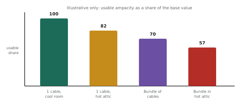
When the conditions are worse than standard, the conductor reaches its rated temperature at a lower current. A hot attic means less temperature difference to drive heat away. A bundle of current-carrying conductors means each conductor is heated by its neighbours. Burial, enclosure in a raceway, and exposure to sunlight all change how easily heat escapes. Correction factors are simply the Code's way of reducing the table value to match the real conditions.
Step 1: from load to required ampacity
Conductor selection starts with the load, not the table. Section 8 tells you how to calculate the load on a branch circuit or feeder, and Rule 8-104 tells you how heavily a circuit may be loaded in relation to the rating of its overcurrent device and conductors. The key idea is continuous load. A load that runs for long periods, such as a grain dryer motor, electric heating or EV charging, heats conductors and breakers more than an intermittent load of the same size. Rule 8-104 therefore limits continuous loads to a fraction of the rating unless the equipment is marked for continuous operation at its full rating.
In practice, for a circuit whose overcurrent device is not marked for continuous duty at its full rating, the continuous load must not exceed a set fraction of the device rating. A common way to express this in study notes is that the required rating is the continuous load divided by the factor. Find the exact factors and conditions in Rule 8-104 of your copy, including the different figure for devices and assemblies marked for continuous operation at full rating, and the separate treatment of conductor ampacity.
Worked problem
Required rating for a continuous load
The Hartley Farms dryer heater draws 38 A continuously. The panel breaker is not marked for continuous duty at its full rating. Using an illustrative continuous-load factor of 0.8, what minimum breaker rating and conductor ampacity does the calculation call for?
Show solution
- Identify the load as continuous: it runs for hours at a time.
- Divide by the illustrative factor: 38 / 0.8 = 47.5 A.
- Choose the next standard breaker rating at or above 47.5 A: 50 A.
- The conductor must have an ampacity suited to the load and to protection by the 50 A device, after corrections; see the next steps.
- Check Rule 8-104 in your copy for the actual factors and the conductor ampacity requirement.
Answer: About 47.5 A required, so a 50 A breaker; the conductor is then chosen in the steps that follow.
Step 2: the base table value
With the required ampacity known, go to the table that matches the conductor material and installation. Tables 1 and 2 cover copper; Tables 3 and 4 cover aluminum. One table in each pair is for conductors in free air and the other for a small number of conductors in a raceway or cable. Read the title of the table and confirm it matches your installation before you read a value. Choose the column by insulation temperature rating, but remember that the column you may finally use can be limited by terminations in Step 4.
Priya's study group uses an invented table for practice so that nobody accidentally memorizes Code values from a slide. The invented table below follows the same structure as the real ones, with sizes labelled A to F instead of AWG numbers.
| Size (illustrative) | 60 C | 75 C | 90 C |
|---|---|---|---|
| A | 15 | 18 | 21 |
| B | 21 | 25 | 28 |
| C | 29 | 35 | 39 |
| D | 41 | 49 | 55 |
| E | 56 | 67 | 75 |
| F | 73 | 87 | 98 |
Step 3: correction factors
Two corrections appear in almost every exam sizing question. The ambient temperature correction from Table 5A applies when the conductor runs through a space hotter than the table's assumed ambient. The grouping correction from Table 5C applies when more current-carrying conductors run together than the base table assumes. Other tables in the 5 series cover other cases; read their titles in your copy so you recognize when they apply. The factors multiply: base value times each factor.
Two counting details catch candidates. First, only current-carrying conductors count toward grouping; a bonding conductor never counts, and a neutral that carries only the unbalanced current of a balanced circuit may not count, depending on the rule. Second, the ambient correction depends on the insulation temperature rating, so a 90 C conductor has a different factor at the same ambient than a 75 C conductor. Look for both details in Rule 4-004 and the table notes.
Step 4: termination limits
Rule 4-006 limits the temperature at which a conductor may be used to the temperature rating of the equipment it connects to. Breakers, panelboard lugs, receptacles and motor terminals all have temperature ratings, and many smaller devices are rated only for 60 C or 75 C. A 90 C conductor terminated on a 75 C lug may have its ampacity corrected from the 90 C column (which helps when correction factors apply), but the value finally used must not exceed the ampacity in the column matching the termination rating.
This is why the 90 C column is still useful even when nothing in the building is rated 90 C. In a hot attic with several cables bundled together, starting from the higher 90 C value and correcting downward often leaves you above the 75 C or 60 C limit, so the termination limit, not the corrections, governs. Without corrections, the termination limit always governs.
Priya's calculator script from MELC-101 does exactly this. The version below adds a size search: give it the required ampacity, the factors and the termination rating, and it returns the smallest invented size that works.
base = {  # invented values for practice only, not from the Code
    'A': {'60': 15, '75': 18, '90': 21},
    'B': {'60': 21, '75': 25, '90': 28},
    'C': {'60': 29, '75': 35, '90': 39},
    'D': {'60': 41, '75': 49, '90': 55},
    'E': {'60': 56, '75': 67, '90': 75},
    'F': {'60': 73, '75': 87, '90': 98},
}

def usable(size, insulation, termination, factors):
    value = base[size][insulation]
    for f in factors:
        value = value * f
    return round(min(value, base[size][termination]), 1)

def smallest(required, insulation, termination, factors):
    for size in base:
        if usable(size, insulation, termination, factors) >= required:
            return size, usable(size, insulation, termination, factors)
    return None

print('Dryer heater, 47.5 A, no corrections, 75 C lugs:', smallest(47.5, '90', '75', []))
print('Same, in a 40 C room (factor 0.91), 6 conductors (0.80):', smallest(47.5, '90', '75', [0.91, 0.80]))Dryer heater, 47.5 A, no corrections, 75 C lugs: ('D', 49)
Same, in a 40 C room (factor 0.91), 6 conductors (0.80): ('E', 54.6)In the first case the termination limit governs and size D works. In the second, the corrections bite: size D corrects to about 40 A, so the script moves up to size E. That jump of one size because of the room temperature and the number of conductors is exactly what exam writers like to test.
Step 5: voltage drop
Ampacity protects the insulation. Voltage drop protects the equipment and the user. A long run can carry its current safely and still deliver too little voltage at the far end, which makes motors run hot and lights dim. Rule 8-102 limits voltage drop in branch circuits and feeders, and Appendix D includes tables (such as Table D3) that help with the calculation. On the exam, voltage drop questions are usually straightforward arithmetic once you know the formula and the limits from your copy.
For a single-phase two-wire circuit, the drop is approximately the current times the resistance of the conductor out and back: twice the one-way length times the resistance per metre times the current. For a balanced three-phase circuit, the factor two is replaced by the square root of three. Resistance values come from a conductor resistance table; the values below are invented.
Worked problem
Voltage drop on the bin yard feeder
A 240 V single-phase feeder to the Hartley Farms bin yard is 95 m long and carries 40 A. The chosen conductor has an illustrative resistance of 0.00082 ohm per metre. What is the voltage drop, and what share of 240 V is it?
Show solution
- Apply the single-phase formula: 2 x 95 x 0.00082 x 40.
- 2 x 95 = 190 m of conductor out and back.
- 190 x 0.00082 = 0.1558 ohm.
- 0.1558 x 40 = 6.23 V.
- As a share of 240 V: 6.23 / 240 = 0.026, which you compare with the limit in Rule 8-102.
Answer: About 6.2 V, or 0.026 of the supply voltage; if that exceeds the limit in your copy, choose a larger conductor.
If the result is over the limit, the fix is a larger conductor, which has lower resistance. On the exam, a question may give you two conductor sizes and ask which is the smallest that meets both the ampacity and the voltage drop requirement. Check ampacity first, then voltage drop, and choose the larger of the two answers.
Neutral conductors and harmonics
The neutral of a single-phase three-wire or three-phase four-wire circuit carries the unbalanced current between the phases. In a perfectly balanced linear load, that current is close to zero. Non-linear loads such as computers, LED drivers and variable frequency drives produce harmonic currents that add in the neutral instead of cancelling. Section 4 contains rules on neutral conductor sizing and on when a neutral counts as a current-carrying conductor for grouping purposes. A neutral serving mainly non-linear loads usually counts, and may need to be as large as or larger than the phase conductors. Look these rules up next to Rule 4-004.
At Hartley Farms the dryer controls include variable frequency drives, so Marcus flags the neutral of the control panel feeder. The group checks the Section 4 neutral rules and agrees to count it as current-carrying and to size it equal to the phases. On the exam, any mention of electronic or non-linear loads on a shared neutral is a signal to read these rules.
Common mistakes
MistakeStarting from the table instead of the load.
InsteadCalculate the load and apply Rule 8-104 first, then size the conductor.
MistakeIgnoring the continuous-load limit.
InsteadContinuous loads need a higher device and conductor rating unless equipment is marked for full-rating continuous duty.
MistakeCounting the bonding conductor as current-carrying.
InsteadBonding conductors never count for grouping; check the rule for neutrals.
MistakeUsing the 90 C value with 75 C terminations.
InsteadCorrect from 90 C if useful, but never exceed the column matching the terminations.
MistakeForgetting voltage drop on long runs.
InsteadCheck Rule 8-102; a conductor that passes ampacity may still fail voltage drop.
Summary and key terms
- Ampacity is the current a conductor carries continuously without exceeding its temperature rating.
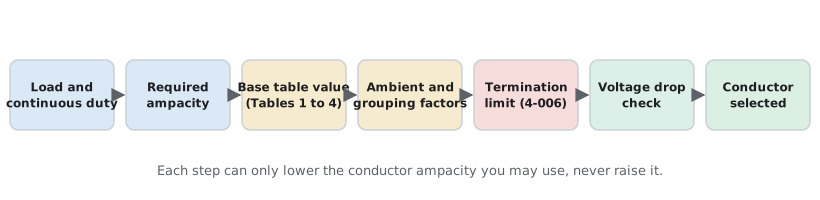
- Selection runs: load, required ampacity (Rule 8-104), base table, corrections (Rule 4-004), termination limit (Rule 4-006), voltage drop (Rule 8-102).
- Correction factors multiply and only current-carrying conductors count toward grouping.
- The 90 C column is useful as a starting point for corrections even with 75 C terminations.
- Neutrals serving non-linear loads usually count as current-carrying and may need full size.
- Ampacity
- The current a conductor can carry continuously in its conditions of use without exceeding its temperature rating.
- Continuous load
- A load expected to run at its maximum current for long periods, limited by Rule 8-104.
- Grouping correction
- The factor that reduces ampacity when more current-carrying conductors run together than the table assumes.
- Termination rating
- The temperature rating of the device or lug a conductor connects to.
- Voltage drop
- The loss of voltage along a conductor caused by its resistance.
Practice problems
Work each problem on paper first, then reveal the answer to check.
Using the invented table, what is the usable ampacity of size C, 90 C insulation, 75 C lugs, no corrections?
Show answer
35 A, limited by the 75 C column.
A continuous load is 30 A and the illustrative factor is 0.8. What rating does the calculation call for?
Show answer
30 / 0.8 = 37.5 A, so the next standard size, 40 A.
Size D (90 C, invented value 55 A) has factors 0.91 and 0.80. What is the corrected value?
Show answer
55 x 0.91 x 0.80 = 40.04, about 40.0 A.
A 120 V circuit is 30 m long, carries 12 A, and the conductor resistance is 0.0052 ohm per metre (invented). What is the drop?
Show answer
2 x 30 x 0.0052 x 12 = 3.74 V.
Why might a neutral count as a current-carrying conductor?
Show answer
Because harmonic currents from non-linear loads add in the neutral instead of cancelling.
Lesson quiz · 5 questions
Score 60% or more to complete this lesson.
Create a free account to save your progress, take quizzes and earn a certificate.