
MELU-106 · Lesson 6 of 12 · 24 min
Solar photovoltaic systems under Article 690
▶ Video coming soon A video version of this lesson is on the way.
Solar photovoltaic, or PV, systems have gone from a specialty to everyday work for electrical contractors, and master exams now include several PV questions on almost every form. Article 690 covers PV systems, including the array circuits, inverters and charge controllers, and it works together with Article 705 for connecting to other sources and Article 706 for energy storage, which lesson 7 covers. PV is different from ordinary wiring in three ways that drive most of the rules: the source cannot simply be switched off, because modules produce voltage whenever light falls on them; the voltage rises as temperature falls, so the coldest morning sets the maximum; and the current is limited by the module, so conductor sizing starts from the module's short-circuit rating rather than a breaker. This lesson covers terminology, maximum voltage, circuit current and conductor sizing, overcurrent protection, disconnects, rapid shutdown, arc-fault and ground-fault protection, and labeling. The Code is cited by number and explained in our own words, and module values in examples are illustrative.
Delgado goes solar
With the finishing line approved, Luis Delgado wants to cut his power bill. His roof can hold about 60 kilowatts of modules, feeding string inverters that connect to the 480Y/277-volt system. Brightwater will partner with a solar installer, but Ray wants Dana to check the design against Article 690 before he signs anything. 'The installer will do the layout,' he says. 'You make sure the voltages, wire sizes and disconnects pass, and that Gloria sees the rapid shutdown labels where she expects them.'
Terminology
Article 690 has rewritten its circuit names several times, which confuses candidates studying from old guides. In current editions, modules are connected in series to form strings, and the DC conductors from the array are collectively called PV system DC circuits. Within that group, PV string circuits run from the modules to a combiner or to the inverter, and the conductors from a combiner onward are often still described as PV output circuits in study materials, though recent editions emphasize the broader term. On the AC side, the conductors from the inverter output to the point of connection are the inverter output circuit. A PV system that connects to the utility-supplied premises wiring is an interactive system, and the point where it meets other sources is governed by Article 705.
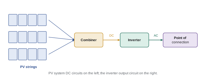
| Part | What it is, in our words |
|---|---|
| PV module | A factory assembly of solar cells that produces DC power |
| String | Modules connected in series to raise the voltage |
| PV system DC circuit | Any DC conductor of the PV system, from modules to inverter |
| Combiner | An enclosure where strings are paralleled, often with fuses |
| Inverter | Equipment that converts DC to AC; interactive inverters synchronize with the utility |
| Inverter output circuit | AC conductors from the inverter to the point of connection |
Maximum system voltage
A module's open-circuit voltage rises as the cells get colder. Section 690.7 requires the maximum PV system DC circuit voltage to be calculated as the sum of the rated open-circuit voltages of the series-connected modules, corrected for the lowest expected ambient temperature. The correction can use the module manufacturer's temperature coefficient for open-circuit voltage, which is the preferred method for crystalline silicon modules, or a table of correction factors in the Code. For systems of 100 kilowatts or larger, a licensed professional engineer may provide a documented calculation. The lowest expected ambient temperature is usually taken from climate data such as the extreme annual mean minimum design dry bulb temperature published for the location.
The maximum voltage then must not exceed limits. PV system DC circuits on or in one- and two-family dwellings are limited to a lower voltage, commonly 600 volts, and other buildings commonly to 1000 volts, with higher voltages allowed in some ground-mounted or utility-scale cases. Every conductor, connector, combiner, disconnect and inverter input must be rated for the calculated maximum voltage.
Worked problem
How many modules per string?
Delgado's design uses modules with an illustrative open-circuit voltage of 49.5 volts at standard test conditions (25 degrees Celsius) and a temperature coefficient of minus 0.0027 per degree Celsius. The lowest expected ambient temperature in Harlow is minus 20 degrees Celsius. The inverter's maximum DC input is 1000 volts. How many modules can be connected in series?
Show solution
- Temperature difference from standard conditions: minus 20 minus 25 is minus 45 degrees.
- Voltage rise factor: 1 plus (minus 0.0027 times minus 45) is 1 plus 0.1215, which is 1.1215.
- Cold open-circuit voltage per module: 49.5 times 1.1215 is about 55.51 volts.
- Maximum modules in series: 1000 divided by 55.51 is about 18.01, so 18 modules.
- Eighteen modules give about 999.2 volts, just under 1000. Dana notes that 17 would leave more margin if the installer prefers.
Answer: 18 modules per string, at most.
# Maximum string length from the module temperature coefficient (illustrative values)
voc_stc = 49.5         # volts at 25 C
coef = -0.0027         # change in Voc per degree C, as a fraction
t_low = -20            # lowest expected ambient, C
v_limit = 1000         # inverter or system limit, volts

factor = 1 + coef * (t_low - 25)
voc_cold = voc_stc * factor
n = int(v_limit // voc_cold)
print(f"Correction factor {factor:.4f}, cold Voc {voc_cold:.2f} V per module")
print(f"Maximum modules in series: {n} (string Voc {n * voc_cold:.1f} V)")
for t in (-30, -10, 0):
    f = 1 + coef * (t - 25)
print(f"At {t} C: {int(v_limit // (voc_stc * f))} modules")Correction factor 1.1215, cold Voc 55.51 V per module Maximum modules in series: 18 (string Voc 999.3 V) At -30 C: 17 modules At -10 C: 18 modules At 0 C: 18 modules
Circuit current and conductor sizing
Section 690.8 sets how PV circuit current is calculated. For PV string circuits, the maximum current is the sum of the parallel module rated short-circuit currents multiplied by 125 out of 100. That first factor accounts for sunlight brighter than standard test conditions. Then, under 690.8(B), conductors and overcurrent devices must be sized for not less than 125 out of 100 of that maximum current, before applying adjustment and correction factors, because PV current is considered continuous. Multiplying the two factors together gives the familiar shortcut of 1.56 times the short-circuit current. The conductor must also carry the maximum current after correction for ambient temperature, which on a rooftop can be high, and adjustment for the number of conductors, and the larger result governs.
Rooftop conductors deserve extra care. Conductors in raceways exposed to sunlight on rooftops can see high temperatures, and the ampacity correction for ambient temperature in 310.15 applies. Many designers keep raceways off the roof surface or use cables listed for the location to avoid steep derating.
Worked problem
Sizing a string conductor
Each string has one module in series path with an illustrative short-circuit current of 13.9 amperes. What is the maximum circuit current, and what minimum conductor ampacity is needed before correction and adjustment?
Show solution
- Maximum current: 13.9 times 1.25 is 17.375 amperes.
- Minimum ampacity before correction and adjustment: 17.375 times 1.25 is about 21.72 amperes.
- Shortcut check: 13.9 times 1.5625 is also about 21.72 amperes.
- Then check the conductor's corrected ampacity against 17.375 amperes using the rooftop ambient temperature and conductor count.
Answer: Maximum current 17.4 amperes; conductor ampacity at least 21.7 amperes before correction.
# PV string current and conductor ampacity (illustrative module)
isc = 13.9          # module short-circuit current, amperes
parallel = 1        # strings in parallel in this circuit

i_max = isc * parallel * 1.25
i_cond = i_max * 1.25
print(f"Maximum circuit current: {i_max:.2f} A")
print(f"Conductor ampacity before correction: {i_cond:.2f} A (shortcut {isc * parallel * 1.5625:.2f} A)")

# After correction: an illustrative 30 A conductor with a 0.76 ambient factor and no adjustment
corrected = 30 * 0.76
print(f"Corrected ampacity {corrected:.1f} A vs maximum current {i_max:.2f} A -> {'OK' if corrected >= i_max else 'too small'}")Maximum circuit current: 17.38 A Conductor ampacity before correction: 21.72 A (shortcut 21.72 A) Corrected ampacity 22.8 A vs maximum current 17.38 A -> OK
Overcurrent protection
Because modules are current-limited, a single string usually cannot overload its own conductors, so overcurrent protection is often not needed for one or two strings. Section 690.9 requires overcurrent protection for PV system DC circuits where the sum of the available fault currents from parallel strings, other sources and any batteries could exceed the ampacity of the conductors or the maximum series fuse rating of the modules. In a combiner with three or more strings in parallel, a fault in one string can be fed by all the others, so each string typically gets a fuse sized at not less than 1.56 times its short-circuit current and not more than the module's maximum series fuse rating. Overcurrent devices on the DC side must be listed for DC use at the system voltage.
Disconnects
Section 690.13 requires a means to disconnect the PV system from all wiring systems, including the building wiring, storage and utilization equipment. The PV system disconnect must be readily accessible, must open all ungrounded conductors simultaneously, and must be marked to show whether it is open or closed and with a label identifying it as a PV system disconnect. Where the line and load terminals may both be energized in the open position, a label must warn of that. Section 690.15 adds isolating devices and equipment disconnects so that equipment such as inverters, combiners and charge controllers can be isolated for service, with rules on their location and type. In practice, many string inverters include an integral DC disconnect that serves as the equipment disconnect.
Rapid shutdown
Rapid shutdown, in section 690.12, protects firefighters who must work on or near a roof with energized PV conductors. It applies to PV system circuits installed on or in buildings. The rule draws an array boundary, commonly 1 foot from the array in all directions. Outside the array boundary, controlled conductors must be reduced to not more than a stated voltage, commonly 30 volts, within a stated time, commonly 30 seconds of initiation. Inside the array boundary, the system must either be a listed PV hazard control system, or reduce controlled conductors to not more than a stated voltage, commonly 80 volts, within 30 seconds, or have no exposed wiring or conductive parts for a stated reach. Module-level power electronics, such as microinverters or DC optimizers with shutdown capability, are a common way to meet the inside-boundary requirement.
The rapid shutdown initiation device must be at a readily accessible location outside the building, often at the service, and for one- and two-family dwellings it is commonly the service disconnect or a dedicated switch near it. Labels are required at the service equipment and at the initiation device, with a specified format, so firefighters know the building has PV with rapid shutdown and what the switch does.
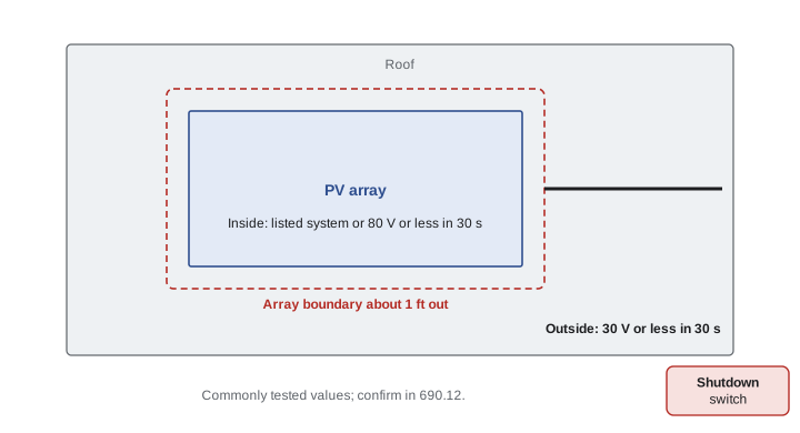
| Item | Commonly tested value (check your edition) |
|---|---|
| Array boundary | 1 ft from the array in all directions |
| Outside the boundary | 30 V or less within 30 seconds |
| Inside the boundary | Listed hazard control system, or 80 V or less within 30 seconds, or other listed method |
| Initiation device | Readily accessible, outside, often at the service |
| Labels | At the service and at the initiation device |
Arc-fault and ground-fault protection
DC arcs do not extinguish themselves the way AC arcs do at each current zero, so a loose connector on a roof can sustain an arc and start a fire. Section 690.11 requires PV systems with DC circuits operating at 80 volts or greater between any two conductors to be protected by a listed PV arc-fault circuit interrupter or other component listed to provide equivalent protection, with exceptions for certain installations not on or in buildings. Section 690.41 requires DC ground-fault detection and interruption for most PV systems, so that a fault from a DC conductor to ground is detected and the fault is interrupted or an indication given. Most listed string inverters include both functions.
Grounding and bonding
PV module frames, racking and other exposed metal parts that could be energized must be connected to an equipment grounding conductor, sized from 250.122 based on the overcurrent device protecting the circuit, or, where there is no overcurrent device, from the PV circuit's short-circuit current. Listed racking systems often include integral bonding means. Where a PV system has a grounding electrode requirement, section 690.47 sets out how the array and the inverter connect to the building's grounding electrode system. Lesson 7 and MELU-104 cover how this interacts with the building's system.
Delgado's design review
Dana's review of the installer's package is short. The strings are 17 modules long, giving extra margin below 1000 volts. The string conductors are sized at 1.56 times the short-circuit current and checked for rooftop temperature with the raceway raised above the roof surface. Each combiner has fuses for its strings. The inverters are listed with integral arc-fault and ground-fault protection and DC disconnects. The modules have listed rapid shutdown devices, and the initiation switch is beside the service, labeled in the required format. She writes one comment: 'Show the AC point of connection and the busbar calculation,' which leads straight to lesson 7.
2026 notes
The 2026 edition continues to reorganize PV, interconnection and storage, with more shared material between Articles 690, 705 and 706 and refinements to rapid shutdown and DC circuit terminology. Some values, such as the dwelling voltage limit and the rapid shutdown thresholds, are frequent proposal topics. Confirm every number in this lesson in your own edition.
Common mistakes
MistakeCalculating maximum voltage at 25 degrees Celsius.
InsteadMaximum voltage is calculated at the lowest expected ambient temperature, when open-circuit voltage is highest.
MistakeSizing PV conductors at 1.25 times the short-circuit current.
InsteadMaximum current is 1.25 times Isc, and conductors are sized at 1.25 times that, or 1.56 times Isc, before correction.
MistakePutting a fuse on a single string without checking whether it is needed.
Instead690.9 requires overcurrent protection only where parallel sources can exceed conductor or module ratings.
MistakePlacing the rapid shutdown initiation switch inside a locked electrical room.
InsteadThe initiation device must be readily accessible, outside the building.
MistakeForgetting arc-fault protection on an 80-volt-or-greater DC system on a building.
Instead690.11 requires listed PV arc-fault protection.
Summary and key terms
- PV sources cannot be switched off at the module, voltage rises in the cold, and current is limited by the module.
- Maximum DC voltage is the sum of open-circuit voltages corrected to the lowest expected ambient temperature.
- Dwellings have a lower DC voltage limit than other buildings; all equipment must be rated for the maximum.
- Maximum circuit current is 1.25 times Isc; conductors and devices are sized at 1.25 times that, or 1.56 times Isc.
- Overcurrent protection is needed where parallel sources can exceed conductor or module ratings.
- Rapid shutdown limits voltage inside and outside the array boundary within 30 seconds of initiation.
- Systems of 80 volts or more on buildings need DC arc-fault protection, and most need ground-fault detection.
- Open-circuit voltage
- The voltage a module or string produces with no load connected.
- Short-circuit current
- The current a module produces with its terminals shorted, used as the basis for PV current calculations.
- Interactive system
- A PV system that operates in parallel with and may deliver power to the utility.
- Rapid shutdown
- A function that reduces the voltage of PV conductors on a building within a set time for firefighter safety.
- Array boundary
- The line, commonly 1 foot outside the array, used to apply rapid shutdown limits.
- Module-level power electronics
- Devices at each module, such as microinverters or optimizers, that can control module output.
Practice problems
Work each problem on paper first, then reveal the answer to check.
A module has an illustrative Voc of 40 volts and a coefficient of minus 0.003 per degree Celsius. What is its Voc at minus 25 degrees Celsius?
Show answer
40 times (1 plus 0.003 times 50), which is 46 volts.
Two strings in parallel each have an Isc of 10 amperes. What is the maximum circuit current?
Show answer
20 times 1.25, which is 25 amperes.
What minimum conductor ampacity, before correction, is needed for that circuit?
Show answer
25 times 1.25, which is 31.25 amperes.
Where must the rapid shutdown initiation device be?
Show answer
At a readily accessible location outside the building, often at the service.
At what DC voltage between conductors does 690.11 arc-fault protection begin to apply?
Show answer
80 volts or greater.
Lesson quiz · 5 questions
Score 60% or more to complete this lesson.
Create a free account to save your progress, take quizzes and earn a certificate.