
MELU-106 · Lesson 10 of 12 · 23 min
Class 1, 2 and 3 circuits and fire alarm systems
▶ Video coming soon A video version of this lesson is on the way.
Not every circuit in a building carries power to a load. Thermostats, door entry systems, nurse call stations, building automation controllers, low-voltage lighting controls, Power over Ethernet devices and fire alarm systems all run on circuits whose power is limited by their source. Chapter 7 of the NEC handles these circuits with rules that relax the wiring method and overcurrent requirements of Chapter 3 because the energy is limited, while adding rules to keep them separated from power circuits and to control the fire performance of their cables. In the 2023 edition, the material that used to be in one large Article 725 was reorganized: Article 722 now holds general requirements for power-limited and fire alarm cables, Article 724 covers Class 1 power-limited circuits, and Article 725 covers Class 2 and Class 3 circuits, with Article 760 covering fire alarm systems. This lesson covers the classes, power sources, separation, cable types and fire alarm rules. Sections are cited by number and explained in our own words; check the arrangement in your edition, because it changed in 2023 and again in 2026.
The Copper Kettle's low-voltage list
The banquet room at the Copper Kettle has a long list of low-voltage work: thermostats for two rooftop units, a door entry and intercom system, a building automation controller for the lighting, several Power over Ethernet cameras and wireless access points, and an addressable fire alarm system extended from the restaurant's panel. Tyler asks Dana why the low-voltage contractor can run cable above the ceiling without conduit when Brightwater's crew cannot. 'Because the source limits the energy,' Dana says. 'But that does not mean anything goes. The cable has to be the right type for the space, it has to stay away from our power wiring, and it cannot hang from the ceiling grid wires.'
The three classes
The classes are defined by the source that supplies them. Class 1 circuits come in two kinds: Class 1 power-limited circuits, supplied by a source with an output limited to a stated voltage, commonly 30 volts, and a stated power, commonly 1000 volt-amperes; and Class 1 remote-control and signaling circuits, which can operate at up to 600 volts and are not power-limited, such as the control circuit of a motor starter. Class 1 circuits are wired much like power circuits, with Chapter 3 wiring methods and overcurrent protection.
Class 2 and Class 3 circuits are supplied by power sources listed for the purpose, such as Class 2 transformers and power supplies, which limit their output so that a fault cannot cause a fire and, for Class 2, contact does not cause a shock hazard. Class 2 circuits operate at lower voltages, commonly up to 30 volts in wet conditions and up to about 60 volts DC in dry conditions, with power commonly limited to 100 volt-amperes. Class 3 circuits allow higher voltages, commonly up to 150 volts, with the same order of power limit, and because shock is possible, they have additional protection requirements. The source's listing and marking tells you the class; you do not calculate it on site.
| Class | Source, in our words | Typical uses | Wiring method |
|---|---|---|---|
| Class 1 power-limited | Limited to about 30 V and 1000 VA | Some industrial controls | Chapter 3 methods |
| Class 1 remote-control and signaling | Not power-limited, up to 600 V | Motor starter control circuits | Chapter 3 methods |
| Class 2 | Listed source; low voltage and power | Thermostats, doorbells, PoE, lighting controls | Listed Class 2 cable or other permitted methods |
| Class 3 | Listed source; higher voltage, limited power | Some intercom and sound systems | Listed Class 3 cable or other permitted methods |
Why limited energy relaxes the rules
Because a Class 2 or Class 3 source cannot deliver enough energy to start a fire in its own wiring, these circuits do not need overcurrent protection on each conductor the way power circuits do, and they may use listed cables installed without raceways. The tradeoff is that the cable must have the right fire performance for the space, so that a fire elsewhere does not travel along the cable or fill an air-handling space with smoke. And because a power circuit could energize a Class 2 conductor if they were mixed, the separation rules are strict.
Separation from power circuits
The separation rules for Class 2 and Class 3 circuits, found in Article 725 Part III, are among the most tested topics in this area. Class 2 and Class 3 conductors must not be placed in any cable, cable tray, compartment, enclosure, manhole, outlet box, device box, raceway or similar fitting with conductors of electric light, power, Class 1, nonpower-limited fire alarm or medium-power broadband communications circuits, unless one of the permitted conditions is met. Those conditions include separation by a barrier, power conductors that enter an enclosure only to connect to the equipment the Class 2 circuits also serve, with a minimum spacing maintained, and the use of cables with stated jackets or insulation in specific arrangements. In hoistways, manholes and other spaces, specific spacing or separation rules apply.
Class 2 and Class 3 cables may be run in the same raceway or cable as each other in many cases, and with communications circuits in some cases, where the cables are listed and the insulation is suitable. Where Class 2 conductors are reclassified as Class 1 by removing their Class 2 markings and treating them under Class 1 rules, they can share space with power circuits under the Class 1 rules, but that choice brings Chapter 3 wiring methods with it.
| Situation | Allowed? |
|---|---|
| Class 2 thermostat cable in the same conduit as 120-volt power | No, unless reclassified or a permitted condition applies |
| Class 2 and power conductors in an enclosure with a fixed barrier between them | Yes |
| Class 2 and Class 3 cables in the same raceway | Generally yes, with listed cables |
| Class 2 cable in a power panel only to reach the controlled equipment, with spacing | Yes, under the stated conditions |
Cable types and where they go
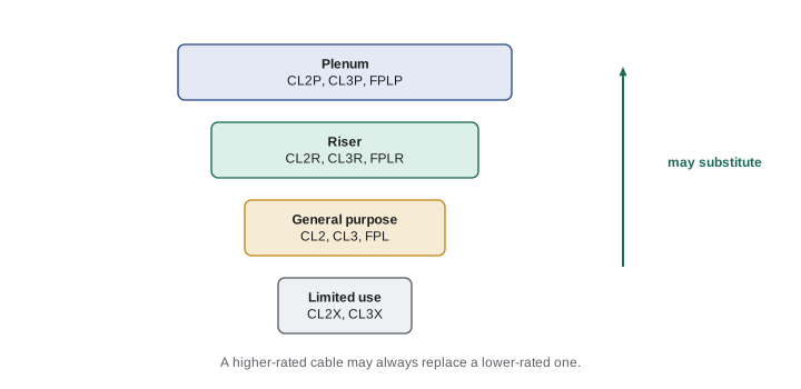
Power-limited cables are listed and marked by fire performance, and Article 722 sets out which type may be used in which space. The general pattern, common to Class 2, Class 3, fire alarm and communications cables, is a hierarchy. Plenum cables, marked with a P such as CL2P or CL3P, have the best fire and smoke performance and may be used in plenums, risers and general spaces. Riser cables, marked with an R such as CL2R or CL3R, are for vertical runs between floors and general use. General-purpose cables, such as CL2 or CL3, are for general use within a floor. Limited-use cables, marked with an X, are for dwellings and short runs in raceways. A higher-rated cable may always substitute for a lower-rated one, and Class 3 cable may substitute for Class 2.
Plenums and other spaces used for environmental air are covered by section 300.22. In a ceiling space used for return air, like the Copper Kettle's, the low-voltage cables must be plenum rated or installed in a raceway suitable for the space. This is a frequent field and exam issue: a CL2 cable above a return-air ceiling is a violation.
| Marking (examples) | Fire rating | Where it may go, in our words |
|---|---|---|
| CL2P, CL3P, FPLP | Plenum | Plenums, risers and general spaces |
| CL2R, CL3R, FPLR | Riser | Vertical shafts between floors and general spaces |
| CL2, CL3, FPL | General purpose | General spaces within a floor |
| CL2X, CL3X | Limited use | Dwellings and short exposed or raceway runs |
Power over Ethernet and cable bundles
Power over Ethernet, or PoE, sends DC power over the same 4-pair cables that carry data, to cameras, access points, LED luminaires and other devices. PoE sources are typically Class 2, but because many cables carrying current can be bundled together, the heat in a large bundle can exceed the cable's temperature rating. Section 725.144 addresses this with a table that gives the ampacity of each conductor in 4-pair cables based on conductor size, temperature rating and the number of cables in a bundle, and with special cable markings, such as an LP suffix with a current rating, for limited-power cables. When the current per conductor exceeds a stated low threshold, the bundle size and cable type must be checked against the table or the cable must be marked LP for the current. Most standard PoE applications fall within the limits, but high-power PoE in large bundles above ceilings needs a check.
Worked problem
Checking a PoE bundle
The Copper Kettle's banquet room will have 24 PoE devices, each drawing up to 0.6 ampere per conductor on 23 AWG, 75-degree cable, run as one bundle for part of the route. Using an illustrative bundle table value of 0.86 ampere per conductor for 23 AWG, 75-degree cable in bundles of 20 to 37 cables, is the bundle acceptable without LP-marked cable?
Show solution
- The current per conductor, 0.6 ampere, is compared with the table value for the bundle size and cable rating.
- The bundle has 24 cables, which falls in the illustrative 20 to 37 range, with a table value of 0.86 ampere.
- 0.6 is less than 0.86, so the bundle is within the illustrative limit.
- Dana checks the real table in her edition and splits the bundle into two smaller bundles anyway, which lowers the temperature rise and leaves room for future devices.
Answer: Yes, within the illustrative limit; check the real table and consider smaller bundles.
# PoE bundle check against an illustrative ampacity table (amperes per conductor)
table_23awg_75c = [(1, 1.2), (8, 1.0), (20, 0.86), (38, 0.76), (62, 0.66), (100, 0.6), (193, 0.5)]   # (min bundle size, limit)

def limit(bundle):
    return [amps for size, amps in table_23awg_75c if bundle >= size][-1]

for bundle, per_conductor in [(24, 0.6), (48, 0.7), (150, 0.6), (6, 0.9)]:
    lim = limit(bundle)
print(f"{bundle} cables at {per_conductor} A: limit {lim} A -> {'OK' if per_conductor <= lim else 'split the bundle or use LP cable'}")24 cables at 0.6 A: limit 0.86 A -> OK 48 cables at 0.7 A: limit 0.76 A -> OK 150 cables at 0.6 A: limit 0.6 A -> OK 6 cables at 0.9 A: limit 1.2 A -> OK
Installation rules for power-limited cables
Power-limited cables still have installation rules. They must be installed in a neat and workmanlike manner and supported by the building structure so that they are not damaged by normal building use, under 722.24 and 300.11. They must not be supported by ceiling grid wires or the ceiling grid itself, unless the support wires are independent and identified for the purpose. Cables must not block access to equipment above suspended ceilings. Penetrations of fire-resistance-rated walls, floors and ceilings must be firestopped to maintain the rating, under 300.21. And the accessible portion of abandoned cables must be removed, because abandoned cable adds fuel to a fire, unless the cable is tagged for future use. Section 722.25 and the corresponding sections for fire alarm and communications cables carry the abandoned cable rule.
Fire alarm systems under Article 760
Article 760 covers the installation of wiring and equipment of fire alarm systems, including all circuits controlled and powered by the fire alarm system. The design of the system, including the number and location of detectors and notification appliances, comes from NFPA 72, the National Fire Alarm and Signaling Code, and the building and fire codes; Article 760 governs the wiring. Fire alarm circuits are either nonpower-limited fire alarm (NPLFA) circuits, wired much like Class 1 circuits, or power-limited fire alarm (PLFA) circuits, wired with listed FPL-type cables much like Class 2 and Class 3 circuits, and the separation rules keep PLFA conductors away from power and NPLFA conductors.
Several fire alarm rules are favorites on exams. The power supply to the fire alarm system must come from a dedicated branch circuit, and the branch circuit disconnecting means must be accessible only to qualified personnel, be identified as a fire alarm circuit, commonly with a red marking, and the location of the circuit disconnect must be permanently identified at the fire alarm control unit. The fire alarm branch circuit must not be supplied through a GFCI or AFCI device, so that a nuisance trip cannot disable the fire alarm. Fire alarm circuits must be identified at terminal and junction locations so they are not unintentionally disturbed during testing and servicing. Where survivability is required by NFPA 72 or the building code, circuit integrity (CI) cable, fire-resistive cable systems or protection with a stated rating are used so the circuit keeps working during a fire for a stated time.
| Fire alarm rule | Summary, in our words |
|---|---|
| Branch circuit | Dedicated to the fire alarm system |
| Disconnect | Accessible only to qualified persons, identified as a fire alarm circuit, location marked at the control unit |
| GFCI or AFCI | Not permitted on the fire alarm branch circuit |
| Cable types | NPLFA for nonpower-limited; FPLP, FPLR or FPL for power-limited |
| Survivability | CI cable or rated fire-resistive systems where NFPA 72 requires |
| Abandoned cable | Accessible portion removed unless tagged for future use |
The banquet room's low-voltage plan
Dana's coordination meeting with the low-voltage and fire alarm contractors produces a short list. All cables above the return-air ceiling are plenum rated. The thermostat cables enter the rooftop units through a separate knockout from the power conductors, and inside the unit the manufacturer's barrier keeps them apart. The PoE cables run in two bundles on J-hooks supported from the structure, not the ceiling wires. The fire alarm extension uses FPLP cable, the panel's circuit breaker in the restaurant panel is locked and marked red, and the location is noted inside the fire alarm control unit door. Gloria's inspection of the ceiling finds only one problem: an old abandoned coaxial cable left from the previous tenant, which the low-voltage contractor removes.
2026 notes
The 2023 edition moved Class 1 to Article 724, Class 2 and 3 to Article 725 and general cable rules to Article 722. The 2026 edition goes further: Chapter 8 communications material is no longer independent of the rest of the Code and much of it is reorganized into Chapter 7, and some articles are renumbered. The concepts in this lesson remain, but the article and section numbers you tab must come from your own edition.
Common mistakes
MistakeRunning thermostat cable in the same conduit as the unit's 208-volt supply.
InsteadClass 2 conductors must be separated from power conductors unless a permitted condition applies.
MistakeInstalling CL2 cable above a return-air ceiling.
InsteadSpaces used for environmental air need plenum-rated cable or a suitable raceway under 300.22.
MistakeSupporting low-voltage cables on the ceiling grid wires.
InsteadCables must be supported by the building structure, not the ceiling grid or its wires.
MistakeProtecting the fire alarm branch circuit with a GFCI breaker.
InsteadArticle 760 prohibits GFCI and AFCI on the fire alarm branch circuit.
MistakeLeaving abandoned cable in a ceiling after a remodel.
InsteadThe accessible portion of abandoned cable must be removed unless tagged for future use.
Summary and key terms
- Class 1, 2 and 3 circuits are defined by their sources; the listing of a Class 2 or Class 3 source decides its class.
- Limited energy allows listed cables without raceways and without per-conductor overcurrent protection.
- Class 2 and Class 3 circuits must be separated from power and Class 1 circuits unless a permitted condition applies.
- Cable fire ratings run from plenum to riser to general purpose to limited use; higher ratings may substitute for lower.
- PoE bundles need a check against the bundle ampacity table or LP-marked cable when currents are significant.
- Fire alarm systems need a dedicated, identified branch circuit without GFCI or AFCI, proper cable types and circuit identification.
- Class 2 circuit
- A circuit supplied by a listed source that limits power so that a fault is not a fire hazard and contact is not a shock hazard.
- Class 3 circuit
- A circuit supplied by a listed source at a higher voltage than Class 2, with limited power and added protection.
- Plenum cable
- A cable with fire and smoke characteristics suitable for spaces used for environmental air.
- Power over Ethernet
- Delivery of DC power over data cables to powered devices.
- PLFA circuit
- A power-limited fire alarm circuit.
- Abandoned cable
- Installed cable that is not terminated at equipment and not identified for future use.
Practice problems
Work each problem on paper first, then reveal the answer to check.
Which cable marking may be used in a plenum: CL2, CL2R or CL2P?
Show answer
CL2P.
May a Class 2 cable share a raceway with 120-volt lighting conductors?
Show answer
Not unless one of the permitted conditions applies or the circuits are reclassified.
What protective device is prohibited on a fire alarm branch circuit?
Show answer
GFCI and AFCI devices.
May a CL3R cable be used where CL2 is specified?
Show answer
Yes. Class 3 may substitute for Class 2 and riser for general purpose.
What must be done with the accessible portion of abandoned low-voltage cable?
Show answer
It must be removed unless tagged for future use.
Lesson quiz · 5 questions
Score 60% or more to complete this lesson.
Create a free account to save your progress, take quizzes and earn a certificate.