
MELU-104 · Lesson 8 of 12 · 23 min
Separately derived systems
▶ Video coming soon A video version of this lesson is on the way.
Delgado Fabrication's expansion needed 120 volt receptacles and lighting in a new machine bay, but the shop's service is 480Y/277 volts. The design called for a 75 kVA dry-type transformer, 480 volt delta primary to 208Y/120 volt wye secondary, feeding a new panelboard. Ray Ochoa handed the grounding to Dana Whitfield as a training exercise, and she discovered what every master candidate eventually learns: a transformer is, for grounding purposes, a new service in the middle of the building. Its secondary has no connection to the utility's grounded conductor, so it needs its own system bonding jumper, its own grounding electrode conductor and its own connection to the building's electrodes. This lesson covers those rules, which are among the most heavily tested in Article 250.
The rules are in 250.30, with sizing from Tables 250.66 and 250.102(C)(1) and bonding of piping and steel in 250.104(D). We explain them in our own words with illustrative values stated as this course's examples. Confirm every requirement and value in your own adopted edition.
What makes a system separately derived
Article 100 defines a separately derived system as an electrical source, other than a service, having no direct connection from its circuit conductors to circuit conductors of other systems, other than through grounding and bonding connections. The test is the circuit conductors, including the grounded conductor. A transformer with separate primary and secondary windings is separately derived, because its secondary circuit conductors are connected to the primary only magnetically. An autotransformer, whose windings share a common conductor, is not. A generator is separately derived only if its grounded conductor is not solidly connected to the normal supply's grounded conductor, which in practice depends on the transfer switch.
Generators cause more confusion than transformers on exams. If the transfer switch switches all the ungrounded conductors but leaves the neutral solidly connected between the generator and the normal service, a three-pole switch on a 208Y/120 volt system for example, the generator's neutral is directly connected to the service neutral. The generator is then not separately derived, and its neutral must not be bonded to its frame at the generator; the system is grounded only at the service, and the generator frame is grounded by the equipment grounding conductor run with the generator conductors. If the transfer switch also switches the neutral, a four-pole switch, the generator is separately derived and needs its own system bonding jumper and grounding electrode connection under 250.30. An informational note in 250.30 reminds you that the manufacturer's bonding arrangement must match the system design, because many portable and standby generators ship with the neutral bonded to the frame.
| Source | Separately derived? | Reason |
|---|---|---|
| Two-winding transformer, 480 V to 208Y/120 V | Yes | No conductor connection between primary and secondary |
| Autotransformer, 240 V to 208 V buck-boost | No | Windings share a conductor |
| Generator with a 3-pole transfer switch, solid neutral | No | Generator neutral is solidly connected to the service neutral |
| Generator with a 4-pole transfer switch, switched neutral | Yes | Generator neutral is not connected to the service neutral |
The system bonding jumper
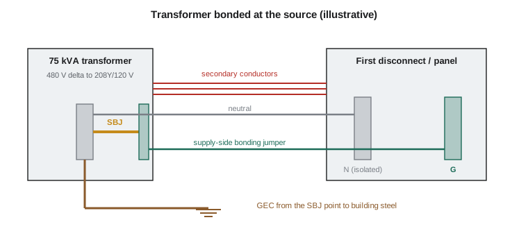
For a grounded separately derived system, 250.30(A)(1) requires an unspliced system bonding jumper that connects the equipment grounding conductors of the derived system to the grounded conductor. It does exactly what the main bonding jumper does at a service: it completes the effective ground-fault current path back to the source, here the transformer secondary. The connection is made at any single point on the separately derived system from the source to the first system disconnecting means or overcurrent device. In practice it is made either at the transformer, in the transformer enclosure, or at the first disconnecting means, in the panelboard or disconnect fed by the transformer.
The phrase single point is the heart of the rule. If the jumper were installed at both the transformer and the first disconnect, the grounded conductor and the equipment grounding path between them would be connected at both ends, forming parallel paths and objectionable current, just as a second bond in a subpanel does. Section 250.30(A)(1) has a narrow exception allowing a bond at both locations where doing so does not establish a parallel path for the grounded conductor, for example where the derived system's grounded conductor and the bonding path are arranged so no metal raceway or other conductive path connects the two enclosures. For exam purposes, remember the rule as one bond, at the source or at the first disconnect, not both.
The system bonding jumper is sized from Table 250.102(C)(1) by the largest ungrounded conductor of the derived system, with the 12.5% rule above the last row, as 250.30(A)(1) and 250.102(C) direct. It must be copper, aluminum or another corrosion-resistant material, and where it is installed at the first disconnecting means, the grounded conductor between the source and the disconnect must be sized at least as large as the jumper, under 250.30(A)(3).
The supply-side bonding jumper and the grounded conductor
When the transformer and its first disconnecting means are in separate enclosures, the metal enclosures need to be bonded together on the supply side of the secondary overcurrent device. Section 250.30(A)(2) requires a supply-side bonding jumper, installed with the derived circuit conductors, sized from Table 250.102(C)(1) by the derived ungrounded conductors. The jumper may be a wire run in the raceway with the secondary conductors, or it may be the metal raceway itself where it qualifies. It is not required to be larger than the derived ungrounded conductors.
Which conductor plays which role depends on where the system bonding jumper is. If the jumper is at the transformer, the neutral and the supply-side bonding jumper run separately to the panelboard, and the panelboard's neutral bar is isolated from its enclosure. If the jumper is at the panelboard, the neutral from the transformer carries the fault current back to the transformer and must be sized at least as large as the table requires under 250.30(A)(3), and the transformer enclosure is bonded through the supply-side bonding jumper.
The grounding electrode and its conductor
Section 250.30(A)(4) requires the derived system to be connected to the building's grounding electrode system. Indoor transformers use the grounding electrode system of the building or structure they are in. Where the building has accessible structural steel or a metal water pipe near the transformer, the conductor runs to it at the nearest practical point, subject to the limits in 250.68(C): metal water piping only within 5 feet of its entry to the building, except in qualified-maintenance commercial and industrial buildings where exposed piping may be used, and structural steel that is itself connected to the electrode system. Outdoor separately derived systems have their own rule in 250.30(C): they get a grounding electrode at the source location, meeting 250.50.
The grounding electrode conductor of a single separately derived system is sized from Table 250.66 by the largest derived ungrounded conductor, under 250.30(A)(5). It connects to the grounded conductor at the same point where the system bonding jumper is connected. That requirement keeps the bonding point, the electrode connection and the fault return path all at one place, which avoids parallel paths.
Worked problem
Grounding a 75 kVA transformer at Delgado
The 75 kVA transformer has a 480 V delta primary and a 208Y/120 V secondary. The secondary conductors are 250 kcmil copper. This example uses 2 AWG copper for the row over 3/0 through 350 kcmil in both Table 250.66 and Table 250.102(C)(1). The system bonding jumper will be at the transformer. Size the system bonding jumper, the grounding electrode conductor and the supply-side bonding jumper.
Show solution
- Largest derived ungrounded conductor: 250 kcmil copper, in the row over 3/0 through 350 kcmil.
- System bonding jumper, from Table 250.102(C)(1): 2 AWG copper in this example.
- Grounding electrode conductor, from Table 250.66: 2 AWG copper in this example, connected at the system bonding jumper point and run to the building steel nearby.
- Supply-side bonding jumper with the secondary conductors, from Table 250.102(C)(1): 2 AWG copper in this example.
Answer: 2 AWG copper for each of the three (check both tables in your edition).
Consider what the transformer's primary side needs. The primary feeder is a normal feeder, protected by an overcurrent device at the 480 volt panel. Its equipment grounding conductor is sized from Table 250.122 by that primary overcurrent device, not from the secondary conductors. For Delgado's transformer, a primary current of 75,000 divided by (480 × 1.732), or 90.2 amperes, protected at 125 amperes, would need the equipment grounding conductor from the row that covers 125 amperes, which this course's example gives as 6 AWG copper.
Several transformers sharing one conductor
Large buildings often have many transformers, and running a full-size grounding electrode conductor from each one back to the electrodes would be wasteful. Section 250.30(A)(6) allows a common grounding electrode conductor with taps. The common conductor must be at least 3/0 AWG copper or 250 kcmil aluminum in this course's examples. Each tap from a transformer to the common conductor is sized from Table 250.66 by that transformer's largest derived ungrounded conductor. The taps connect to the common conductor by listed irreversible compression connectors, exothermic welding or a copper busbar of at least the dimensions the section specifies, so the common conductor stays continuous. The common conductor may also be the building's structural steel or interior metal water pipe that meets 250.68(C).
Worked problem
Three transformers on a common conductor
The Harlow Commons renovation adds three transformers whose largest secondary conductors are 3/0 AWG, 250 kcmil and 500 kcmil copper. This example uses 4 AWG for 2/0 and 3/0, 2 AWG for over 3/0 through 350 kcmil, and 1/0 AWG for over 350 through 600 kcmil. Size the common conductor and each tap.
Show solution
- Common grounding electrode conductor: at least 3/0 AWG copper.
- Tap from the 3/0 transformer: 4 AWG copper.
- Tap from the 250 kcmil transformer: 2 AWG copper.
- Tap from the 500 kcmil transformer: 1/0 AWG copper.
Answer: A 3/0 copper common conductor with taps of 4 AWG, 2 AWG and 1/0 AWG copper.
Bonding piping and steel near the derived system
Section 250.104(D) requires metal water piping and exposed structural metal in the area served by a separately derived system to be bonded to the derived system's grounded conductor at the same point the grounding electrode conductor connects. The jumper is sized from Table 250.102(C)(1) by the derived ungrounded conductors. Where the building steel or the water pipe already serves as the grounding electrode for that system, the separate bond is not needed. The goal is the same as at the service: everything metal in the area served by the new system rises and falls together.
Ungrounded separately derived systems
Section 250.30(B) covers derived systems that are permitted to operate ungrounded, such as a 480 volt delta secondary feeding only three-phase motors in a plant with qualified maintenance. There is no system bonding jumper, because no conductor is grounded. The equipment is still bonded and grounded, and a grounding electrode conductor connects the metal enclosures of the derived system to the grounding electrode, sized from Table 250.66 by the derived conductors. Lesson 10 covers the ground detectors such systems need.
A calculator you can edit
The listing below finds the secondary and primary currents of a transformer and sizes the bonding jumper, grounding electrode conductor and primary equipment grounding conductor from this lesson's illustrative rows. Change the kVA and conductor sizes to practice.
import math

def three_phase_amps(kva, volts):
    return kva * 1000 / (math.sqrt(3) * volts)

GEC_ROWS = [(133.1, "6 AWG"), (167.8, "4 AWG"), (350, "2 AWG"), (600, "1/0 AWG")]   # illustrative
EGC_ROWS = [(60, "10 AWG"), (100, "8 AWG"), (200, "6 AWG"), (300, "4 AWG")]        # illustrative

def row(rows, value):
    return next(size for limit, size in rows if value <= limit)

kva = 75
print(f"Secondary current: {three_phase_amps(kva, 208):.1f} A at 208 V")
print(f"Primary current: {three_phase_amps(kva, 480):.1f} A at 480 V")
secondary_kcmil = 250
print("System bonding jumper and GEC:", row(GEC_ROWS, secondary_kcmil), "copper")
print("Primary feeder EGC (125 A device):", row(EGC_ROWS, 125), "copper")
for k in (167.8, 250, 500):
print(f"Tap for {k} kcmil secondary: {row(GEC_ROWS, k)}")Secondary current: 208.2 A at 208 V Primary current: 90.2 A at 480 V System bonding jumper and GEC: 2 AWG copper Primary feeder EGC (125 A device): 6 AWG copper Tap for 167.8 kcmil secondary: 4 AWG Tap for 250 kcmil secondary: 2 AWG Tap for 500 kcmil secondary: 1/0 AWG
Common mistakes
MistakeBonding the neutral to the enclosure at both the transformer and the panelboard.
InsteadInstall the system bonding jumper at one point only, at the source or the first disconnect.
MistakeSizing the transformer's grounding electrode conductor from the primary overcurrent device.
InsteadUse Table 250.66 with the largest derived ungrounded conductor.
MistakeBonding a generator's neutral to its frame when the transfer switch does not switch the neutral.
InsteadA generator with a solidly connected neutral is not separately derived; it is grounded only at the service.
MistakeRunning a common grounding electrode conductor smaller than the minimum.
InsteadA common conductor for multiple derived systems must be at least 3/0 copper or 250 kcmil aluminum in this course's examples; taps are sized individually.
MistakeConnecting the grounding electrode conductor at a different point from the system bonding jumper.
InsteadSection 250.30(A)(5) requires the connection at the same point as the system bonding jumper.
Summary and key terms
- A separately derived system has no direct connection of its circuit conductors to another system, other than through grounding and bonding; most two-winding transformers qualify.
- Generators are separately derived only when the transfer switch switches the neutral.
- A system bonding jumper is installed at one point, at the source or the first disconnect, sized from Table 250.102(C)(1) by the derived conductors.
- A supply-side bonding jumper bonds separate source and disconnect enclosures, also sized from Table 250.102(C)(1).
- The grounding electrode conductor is sized from Table 250.66 by the derived conductors and connects at the system bonding jumper point to the building's electrode system.
- Multiple derived systems may share a common conductor of at least 3/0 copper, with individually sized taps; the primary feeder's equipment grounding conductor uses Table 250.122.
- Separately derived system
- A source other than a service with no direct connection of its circuit conductors to another system's conductors.
- System bonding jumper
- The connection between the grounded conductor and the equipment grounding conductors at a separately derived system.
- Supply-side bonding jumper
- A bonding conductor on the supply side of the derived system's overcurrent device that bonds metal enclosures.
- Common grounding electrode conductor
- A single conductor serving several separately derived systems through taps.
- Switched neutral
- A transfer switch arrangement that opens the neutral along with the ungrounded conductors.
Practice problems
Work each problem on paper first, then reveal the answer to check.
A 45 kVA transformer has 3/0 AWG copper secondary conductors. This course's row for 2/0 and 3/0 is 4 AWG copper. Size its system bonding jumper and grounding electrode conductor.
Show answer
4 AWG copper for each, from Tables 250.102(C)(1) and 250.66.
Find the secondary current of a 112.5 kVA, 208Y/120 V transformer.
Show answer
112,500 ÷ (208 × 1.732) = 312.3 A.
A standby generator connects through a transfer switch that switches only the three ungrounded conductors. Where is the neutral bonded?
Show answer
Only at the service; the generator is not separately derived.
Four transformers share a common grounding electrode conductor. What is its minimum copper size in this course's examples?
Show answer
3/0 AWG copper, with each tap sized from Table 250.66 by its own secondary conductors.
Where must the grounding electrode conductor of a derived system connect to the grounded conductor?
Show answer
At the same point where the system bonding jumper is connected.
Lesson quiz · 5 questions
Score 60% or more to complete this lesson.
Create a free account to save your progress, take quizzes and earn a certificate.