
MELU-104 · Lesson 10 of 12 · 23 min
Ungrounded and high-impedance systems
▶ Video coming soon A video version of this lesson is on the way.
Every system Dana Whitfield had installed in eleven years at Brightwater Electric was solidly grounded. So when her practice exam asked what happens on an ungrounded 480 volt system when one phase faults to a motor frame, she picked the answer she would expect from a grounded system: the breaker trips. It does not. On an ungrounded system, the first ground fault draws only a tiny current, nothing trips, the motor keeps running, and the other two phases rise to 480 volts above ground. Ray Ochoa had worked in a paper mill early in his career, where 480 volt ungrounded and high-impedance grounded systems were normal, and he walked her through why plants choose them, what the code demands in return, and what the exam tests. This lesson is his explanation, organized around 250.20, 250.21, 250.26 and 250.36.
As always, the rules are summarized in our own words with illustrative values stated as this course's examples. Confirm every condition and value in your own adopted edition.
Why anyone would choose an ungrounded system
A solidly grounded system clears a ground fault immediately by tripping the circuit. That is ideal for safety in most buildings, but in some industrial processes an unexpected shutdown is itself dangerous or very expensive. A glass furnace that loses power solidifies. A chemical reactor that loses its cooling pumps can run away. A continuous paper machine that stops can take a day to restart. For processes like these, an ungrounded system offers continuity: the first ground fault does not trip anything, so the process keeps running while maintenance staff find and repair the fault on their schedule.
The price of that continuity is a hidden hazard. While the first fault is in place, the system is effectively corner grounded through the fault, and the two unfaulted phases sit at full line-to-line voltage above ground. If a second ground fault occurs on a different phase, the two faults together form a phase-to-phase short circuit through the equipment frames and the bonding conductors, with large currents and possibly arcing at two separate locations. The code therefore permits ungrounded systems only in limited cases and requires ground detectors so the first fault is found and fixed before a second one happens.
When a system may be ungrounded
Lesson 3 covered 250.20(B), which requires grounding for systems where the voltage to ground can be held at 150 volts or less, for four-wire wye systems using the neutral, and for four-wire delta systems using a winding midpoint. Systems that fall outside those conditions, such as a 480 volt three-phase, three-wire delta, are not required to be grounded. Section 250.21(A) lists systems that are permitted to be grounded but are not required to be: systems used exclusively to supply industrial electric furnaces for melting, refining, tempering and similar purposes; separately derived systems used exclusively for rectifiers that supply only adjustable-speed industrial drives; separately derived systems supplied by transformers with primaries under 1,000 volts, used for control circuits, where only qualified persons service the installation, ground detectors are installed, and continuity of control power is required; and other systems that 250.20(B) does not require to be grounded.
Ground detectors and marking
Section 250.21(B) requires ground detectors on ungrounded alternating current systems permitted by 250.21(A)(1) through (A)(4) that operate at not less than 120 volts and not more than 1,000 volts. The detectors are installed as close as practicable to where the system receives its supply. A simple ground detector is a set of three lamps or voltmeters, one connected from each phase to ground. In normal operation all three show the same reading. When one phase faults to ground, its lamp goes dark and the other two burn brighter, because their voltage to ground rises from line-to-neutral to line-to-line. Modern installations use insulation monitoring relays that alarm and indicate which phase has faulted.
Section 250.21(C) requires ungrounded systems to be legibly marked at the source or first disconnecting means of the system to identify the system as ungrounded and state the operating voltage between conductors. The marking must be durable for the environment. The purpose is simple: a worker who assumes a system is grounded may assume a phase reads 277 volts to ground when it can read 480.
Worked problem
What a ground detector shows
A 480 V ungrounded delta system at a plant Ray once worked at has a three-lamp ground detector. In normal operation, each phase sits at about the line-to-neutral voltage to ground through the system's capacitance. Phase B then faults solidly to a motor frame. What does each lamp read before and after the fault?
Show solution
- Before the fault, each phase is about 480 ÷ 1.732 = 277 V to ground, so all three lamps glow equally.
- After the fault, phase B is at ground potential, so its lamp reads about 0 V and goes dark.
- Phases A and C are now 480 V above ground, the full line-to-line voltage, so their lamps burn brighter.
- Nothing trips; the alarm, or the dark lamp, is the only sign of the fault.
Answer: About 277 V on each before; after the fault, about 0 V on B and 480 V on A and C.
Ground detectors only help if someone responds to them. Ray's old mill had a written procedure: when the detector alarmed, an electrician was dispatched within the shift, feeders were opened one at a time during a planned window until the alarm cleared, and the faulted circuit was repaired before the next production run. The code does not prescribe that procedure, but it is why 250.21(A)(3) and 250.36 tie these systems to qualified persons. On an exam, a scenario with an ungrounded system and no one assigned to watch the detector is describing exactly the hidden hazard the code is trying to prevent.
Corner-grounded delta systems
A three-phase, three-wire delta system may also be grounded by connecting one phase conductor to ground, a corner-grounded delta. Section 250.26 tells you which conductor is grounded on each type of system, and for a three-phase, three-wire delta, it is one phase conductor. The grounded phase must be identified as a grounded conductor, white or gray, and the overcurrent rules in Article 240 forbid placing an overcurrent device in that grounded conductor except where it opens all conductors simultaneously. Corner-grounded systems clear a ground fault on either ungrounded phase like any grounded system, but they are uncommon today, and a worker who assumes a phase-to-ground reading of 277 volts on a 480 volt corner-grounded system will be wrong: the two ungrounded phases read 480 volts to ground.
High-impedance grounded neutral systems
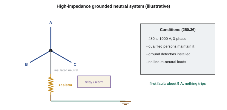
High-impedance grounding offers a middle path. Instead of leaving the system ungrounded or connecting the neutral solidly to ground, the neutral point is connected to ground through a resistor that limits ground-fault current to a few amperes. A first ground fault then draws a small, controlled current that does not trip the circuit, so the process continues, but the current is large enough to detect and locate easily, and the resistor keeps the system's voltage to ground stable, which prevents the dangerous transient overvoltages that can build up on truly ungrounded systems during intermittent arcing faults.
Section 250.36 permits high-impedance grounded neutral systems for three-phase alternating current systems of 480 volts to 1,000 volts, where three conditions are met: the conditions of maintenance and supervision ensure that only qualified persons service the installation, ground detectors are installed on the system, and line-to-neutral loads are not served. The third condition is the one exam writers like. A high-impedance grounded system cannot serve 277 volt lighting, because the neutral is not solidly grounded and would not hold a stable voltage to ground under load; the lighting must be served from a separately derived, solidly grounded system, such as a transformer.
The installation rules follow from how the system works. The grounding impedance is installed between the grounding electrode conductor and the system neutral point; where no neutral exists, the neutral point is derived from a grounding transformer. The neutral conductor from the neutral point to the impedance must be fully insulated, have an ampacity at least equal to the maximum current rating of the impedance, and in this course's examples be not smaller than 8 AWG copper or 6 AWG aluminum. The system neutral may not be connected to ground except through the impedance. An unspliced equipment bonding jumper connects the equipment grounding conductors to the grounded side of the impedance, and the grounding electrode conductor connects anywhere from the grounded side of the impedance to the equipment grounding connection at the service or first disconnecting means.
Sizing the grounding resistor
The design of the resistor is an engineering matter, but master exams sometimes ask for the arithmetic. The resistor is chosen so that the ground-fault current it allows is slightly larger than the system's capacitive charging current, the small current that flows to ground through the capacitance of cables and motor windings. Allowing a resistive current at least equal to the charging current damps the transient overvoltages. On a 480 volt system, charging currents of 1 to 5 amperes are typical, and resistors are commonly sized for a few amperes more.
Worked problem
Choosing a grounding resistor
A 480Y/277 V system at a plant has a measured charging current of 2.5 A. The engineer wants the resistor to allow 5 A during a ground fault. What resistance is needed, and how much power does the resistor dissipate during a fault?
Show solution
- During a solid ground fault, the full line-to-neutral voltage, about 277 V, appears across the resistor.
- Resistance: R = V ÷ I = 277 ÷ 5 = 55.4 Ω.
- Power during the fault: P = V × I = 277 × 5 = 1,385 W, which the resistor must be rated to dissipate continuously, because the fault may remain while the process runs.
Answer: About 55.4 Ω, dissipating about 1,385 W during a fault.
Note that the fault current is fixed by the resistor at 5 amperes no matter where the fault is. That is the point. Compare that with a solidly grounded system, where the same fault might draw thousands of amperes and trip a feeder, or an ungrounded system, where the fault draws only the 2.5 amperes of charging current and can let the system's voltage to ground swing dangerously during intermittent arcing.
| Feature | Solidly grounded | High-impedance grounded | Ungrounded |
|---|---|---|---|
| First ground fault current | Very large; circuit trips | A few amperes, set by the resistor | Capacitive charging current only |
| Process continuity on first fault | No | Yes | Yes |
| Line-to-neutral loads permitted | Yes | No | No neutral to serve them |
| Transient overvoltage on arcing faults | Low | Low | Can be high |
| Ground detectors required | No | Yes | Yes |
A calculator you can edit
The listing below computes the phase-to-ground voltages on an ungrounded system before and after a fault, and sizes a grounding resistor for a chosen fault current. Change the voltage and currents to practice.
import math

def line_to_neutral(v_ll):
    return v_ll / math.sqrt(3)

def resistor(v_ll, fault_amps):
    v = line_to_neutral(v_ll)
    return v / fault_amps, v * fault_amps

v_ll = 480
print(f"Normal: each phase about {line_to_neutral(v_ll):.0f} V to ground")
print(f"After one phase faults: faulted phase 0 V, others {v_ll} V to ground")
for charging in (1.5, 2.5, 4.0):
    target = 2 * charging
    ohms, watts = resistor(v_ll, target)
print(f"Charging {charging} A -> resistor for {target} A: {ohms:.1f} ohms, {watts:.0f} W during a fault")Normal: each phase about 277 V to ground After one phase faults: faulted phase 0 V, others 480 V to ground Charging 1.5 A -> resistor for 3.0 A: 92.4 ohms, 831 W during a fault Charging 2.5 A -> resistor for 5.0 A: 55.4 ohms, 1386 W during a fault Charging 4.0 A -> resistor for 8.0 A: 34.6 ohms, 2217 W during a fault
Common mistakes
MistakeExpecting the breaker to trip on the first ground fault of an ungrounded system.
InsteadThe first fault draws only charging current; nothing trips, and the other phases rise to line-to-line voltage.
MistakeServing 277 V lighting from a high-impedance grounded system.
InsteadSection 250.36 permits high-impedance grounding only where no line-to-neutral loads are served.
MistakeOmitting ground detectors on an ungrounded 480 V system.
InsteadSection 250.21(B) requires ground detectors on ungrounded systems from 120 to 1,000 V.
MistakeLeaving out equipment grounding on an ungrounded system.
InsteadEquipment must still be bonded and grounded so a second fault clears.
MistakeBonding the neutral of a high-impedance system directly to ground somewhere downstream.
InsteadThe neutral may reach ground only through the impedance.
Summary and key terms
- Ungrounded and high-impedance grounded systems keep a process running through a first ground fault, at the cost of a hidden hazard until the fault is fixed.
- Section 250.21(A) lists systems permitted, but not required, to be grounded; 250.21(B) requires ground detectors from 120 to 1,000 V, and 250.21(C) requires marking.
- On an ungrounded system, a first fault leaves the other two phases at line-to-line voltage to ground; a second fault on another phase becomes a short circuit through equipment.
- A corner-grounded delta grounds one phase conductor, identified as a grounded conductor.
- High-impedance grounding under 250.36 is permitted at 480 to 1,000 V three-phase with qualified maintenance, ground detectors and no line-to-neutral loads.
- The grounding resistor limits fault current to a few amperes, usually just above the system's charging current.
- Ungrounded system
- A system with no circuit conductor intentionally connected to ground.
- Ground detector
- A device that indicates a ground fault on an ungrounded or impedance grounded system.
- High-impedance grounded neutral system
- A system whose neutral point is grounded through a resistor that limits ground-fault current to a low value.
- Charging current
- The small current that flows to ground through the capacitance of a system's cables and equipment.
- Corner-grounded delta
- A three-phase, three-wire delta system with one phase conductor intentionally grounded.
Practice problems
Work each problem on paper first, then reveal the answer to check.
On a 600 V ungrounded delta system, what are the phase-to-ground voltages after a solid fault on phase A?
Show answer
Phase A 0 V; phases B and C 600 V to ground.
Find the resistor for a 480Y/277 V high-impedance system designed to allow 4 A of ground-fault current.
Show answer
277 ÷ 4 = 69.3 Ω, dissipating 277 × 4 = 1,108 W during a fault.
Name the three conditions for a high-impedance grounded neutral system under 250.36.
Show answer
Qualified persons maintain it, ground detectors are installed, and no line-to-neutral loads are served.
What marking does 250.21(C) require on an ungrounded system?
Show answer
A durable marking at the source or first disconnect identifying the system as ungrounded and stating the voltage between conductors.
How is 277 V lighting served in a plant with a high-impedance grounded 480 V system?
Show answer
From a separately derived, solidly grounded system, such as a 480 V to 480Y/277 V or 208Y/120 V transformer.
Lesson quiz · 5 questions
Score 60% or more to complete this lesson.
Create a free account to save your progress, take quizzes and earn a certificate.