
HSE-219 · Lesson 4 of 12 · 29 min
How cranes stay up: stability, load charts and ground
A mobile crane is a balance. On one side is the load, hanging at the end of a long boom. On the other side are the crane's own weight and its counterweight. Between them is a tipping line, usually the line through the outrigger floats or the edge of the tracks on the side of the load. As long as the crane's stabilizing moment exceeds the load's overturning moment, the crane stays upright. This lesson explains that balance, how the load chart describes it, and why the ground under the crane matters as much as the crane itself.
The calculations here are for understanding. The manufacturer's load chart, operator's manual and outrigger load information always govern, and lift calculations for critical lifts are prepared by competent people using the actual chart for the crane on site.
Moments and the tipping line
A moment is a force multiplied by the distance from a pivot. The load creates an overturning moment about the tipping line equal to its weight times its horizontal distance beyond that line. The crane's weight and counterweight create a stabilizing moment equal to their weight times their distance behind the line.
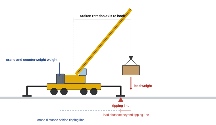
Several things increase the overturning moment without anyone touching the load: booming down or telescoping out increases the radius; the boom deflects under load, which pushes the hook outward; the load swings outward when the crane slews quickly; wind pushes on the load and boom; and a crane set up out of level moves the load further out on the downhill side. Every one of these effects is small, and every one of them has contributed to overturns.
Radius: the most important number
The radius is the horizontal distance from the crane's centre of rotation to the centre of the hook, with the load suspended. It is not the distance from the edge of the crane, and it is not the boom length. Capacity falls quickly as radius grows, so a few metres of error can turn a safe lift into an overturn.
Worked problem
Radius grows when the load is lifted
A telescopic boom is 30 m long at an angle of 60 degrees. The boom foot pin is 1.5 m behind the centre of rotation. Estimate the radius, then estimate it again if the boom deflects so that the effective angle drops to 57 degrees under load.
Show solution
- Horizontal reach of the boom: \( 30 \cos 60^{\circ} = 15.0 \) m.
- Radius: \( 15.0 - 1.5 = 13.5 \) m.
- Under load: \( 30 \cos 57^{\circ} = 16.3 \) m, so the radius becomes \( 16.3 - 1.5 = 14.8 \) m.
- The radius grew by 1.3 m, about 10 per cent, just from boom deflection.
Answer: About 13.5 m unloaded and about 14.8 m loaded. Load charts are based on the loaded radius, which is why operators measure radius with the load suspended, and why planners allow a margin.
Reading a load chart
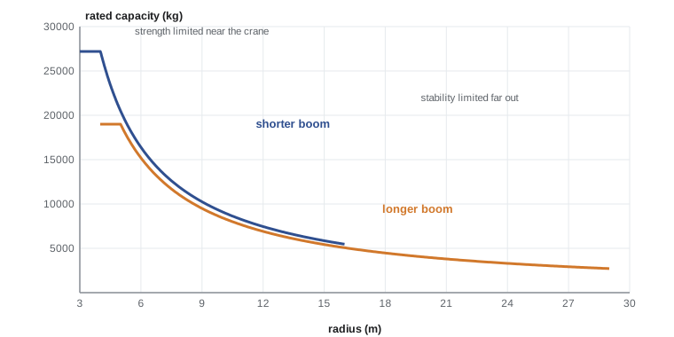
A load chart is the manufacturer's table of rated capacities. It is specific to the crane model, and often to the serial number. A typical chart for a telescopic crane lists boom lengths across the top, radii down the side, and capacities in the body of the table, for one particular configuration of outriggers and counterweight and one working area, such as 360 degrees or over the rear only.
| Radius (m) | Boom 12.2 m | Boom 18.3 m | Boom 24.4 m | Boom 30.5 m |
|---|---|---|---|---|
| 4 | 27,200 | 24,500 | — | — |
| 6 | 19,100 | 18,600 | 16,300 | — |
| 8 | 13,600 | 13,400 | 12,700 | 11,300 |
| 10 | — | 10,200 | 9,800 | 8,900 |
| 12 | — | 7,900 | 7,700 | 7,100 |
| 14 | — | 6,200 | 6,100 | 5,700 |
| 16 | — | — | 4,900 | 4,600 |
Three features of real charts are easy to miss:
- Charts usually mark which capacities are limited by structural strength and which by stability. Near the crane, the boom or another component would fail before the crane tipped; far out, the crane would tip first. Either way the chart value is the limit, but it explains why a crane can collapse without tipping when overloaded at short radius.
- Chart capacities already include a margin below the tipping point. For example, ASME B30.5 bases capacities on outriggers at no more than 85 per cent of the tipping load and on crawlers at no more than 75 per cent. That margin covers dynamic effects and small errors. It is not spare capacity.
- The notes are part of the chart. They state what must be deducted, the conditions such as level within a stated tolerance, the maximum wind speed and which configurations are allowed. A capacity read without the notes is meaningless.
Deductions: what counts as load
Everything hanging below the boom tip counts as load. The chart capacity is the gross capacity; the net capacity available for the item being lifted is what remains after deductions. Typical deductions include the hook block or headache ball, the slings, shackles and spreader beam, and, on many cranes, a stowed or erected jib and auxiliary boom head even when the load is on the main hoist.
Worked problem
Net capacity and percentage of chart
Using the illustrative kilogram chart, a crane with a 24.4 m boom must place a 6,100 kg air handling unit at a loaded radius of 12 m. Deductions are: hook block 350 kg, spreader beam and slings 280 kg, stowed jib deduction from the chart notes 410 kg. Is the lift within capacity, and what percentage of the chart is used?
Show solution
- Chart capacity at 12 m with a 24.4 m boom: 7,700 kg.
- Total deductions: \( 350 + 280 + 410 = 1040 \) kg.
- Net capacity for the load: \( 7700 - 1040 = 6660 \) kg.
- The unit is 6,100 kg, which is within the net capacity.
- Total gross load: \( 6100 + 1040 = 7140 \) kg, which is \( \tfrac{7140}{7700} \times 100 = 92.7 \) per cent of chart.
Answer: It is within capacity, but at about 93 per cent of chart it is a critical lift by most definitions. A small error in the unit's weight or the radius could put it over. Consider a shorter radius, a larger crane or removing the jib.
Configuration and working area
A crane's capacity changes with its configuration. Outriggers that are only partly extended, reduced counterweight, a different boom mode or working over the side instead of over the rear can each cut capacity sharply. Many cranes now allow partial outrigger extension with a matching chart, and the load moment indicator must be set to the configuration actually used. A wrong setting tells the operator the crane has capacity it does not have.
Working areas matter too. Some cranes have more capacity over the rear than over the side or front, and some charts forbid lifting over the front at all. When a load is swung from the rear to the side, the capacity can drop below the load mid-swing. Lift planning must check the capacity for the worst position along the whole swing, not just at pickup and set-down.
Ground: the foundation of every lift
A crane is only as stable as the ground under it. When the load swings over an outrigger, that outrigger may carry most of the crane's weight plus the load. If the ground under it settles, the crane tilts, the radius grows and the overturning moment increases. That can start a chain that ends in an overturn within seconds.
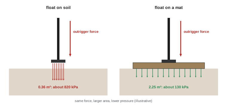
The pressure an outrigger puts on the ground is its load divided by the area that carries it.
Worked problem
Outrigger pressure with and without a mat
The manufacturer's outrigger load calculator shows a maximum outrigger force of 30 tonnes (about 294 kN) during a planned lift. The outrigger float is 0.6 m by 0.6 m. The site has compacted granular fill that a geotechnical engineer has said can safely take 200 kPa. Is the float alone acceptable? What size of mat would be needed?
Show solution
- Float area: \( 0.6 \times 0.6 = 0.36 \) m².
- Pressure: \( p = \tfrac{294}{0.36} = 817 \) kPa, about four times the allowable 200 kPa.
- Required area: \( A = \tfrac{294}{200} = 1.47 \) m².
- A square mat at least \( \sqrt{1.47} = 1.21 \) m on a side is needed, assuming the mat is stiff enough to spread the load evenly. A 1.5 m by 1.5 m mat gives \( \tfrac{294}{2.25} = 131 \) kPa.
Answer: The float alone is far over the allowable pressure. A stiff mat of about 1.5 m by 1.5 m brings the pressure to about 130 kPa. The mat's stiffness and the ground value must come from competent sources, not guesses.
| Ground type | Indicative allowable bearing pressure | Notes |
|---|---|---|
| Soft clay, peat, fresh fill | Below 75 kPa | Needs engineered solutions; avoid if possible |
| Firm clay, loose sand | About 75 to 150 kPa | Varies with moisture; rain and thaw reduce it |
| Compacted granular fill, dense sand and gravel | About 200 to 400 kPa | Only if compaction is confirmed |
| Sound bedrock | Over 1,000 kPa | Watch for voids and fractured rock |
Hidden hazards under the surface
The most dangerous ground is the ground that looks fine. Backfilled trenches, buried tanks, basements, culverts, catch basins, old foundations, utility vaults and recently compacted fill can all collapse under an outrigger. Asphalt and concrete slabs can crack and punch through. Frozen ground can be very strong in the morning and weak by afternoon. Edges of excavations and retaining walls are especially risky because the soil near them can slide toward the opening, a topic covered in HSE-217.
In Canada, the employer, the constructor and the crane owner share responsibility for confirming the ground is adequate. CSA Z150 and manufacturers require the crane to be level within a tight tolerance and on firm, supporting ground. On many sites, the constructor provides a crane pad or a geotechnical assessment for planned crane locations.
Before a crane sets up, someone should confirm with drawings, locates and a walk of the area that nothing is buried under the outrigger positions. During the lift, a person should watch the outriggers and mats for settlement and stop the lift if any sign appears.
Common mistakes
MistakeMeasuring radius from the edge of the crane or using boom length.
InsteadRadius is the horizontal distance from the centre of rotation to the hook, with the load suspended.
MistakeReading the chart capacity without subtracting the block, rigging and jib.
InsteadEverything below the boom tip counts; subtract deductions to find net capacity.
MistakeTreating the margin built into the chart as spare capacity.
InsteadThe margin covers dynamic effects and small errors; the chart value is the limit.
MistakeChecking capacity only at pickup and set-down.
InsteadCheck the worst position along the whole swing and working area.
MistakeSetting outriggers on unknown ground without mats.
InsteadConfirm ground capacity and buried hazards, and use properly sized mats.
Summary and key terms
- A crane stays upright while the stabilizing moment of the crane and counterweight exceeds the overturning moment of the load about the tipping line.
- Radius, measured with the load suspended, controls capacity; boom deflection, swing and out-of-level setup all increase it.
- Load charts are specific to the crane and configuration, include a margin and must be read with their notes.
- Net capacity equals chart capacity minus the hook block, rigging and other deductions.
- Configuration and working area can cut capacity sharply; check the worst point of the swing.
- Outrigger pressure equals force divided by area; mats spread the load, and buried hazards must be ruled out.
- Moment
- A force multiplied by its distance from a pivot.
- Tipping line
- The line about which a crane would overturn, usually through the outriggers or track edge on the load side.
- Radius
- The horizontal distance from the centre of rotation to the centre of the hook with the load suspended.
- Gross capacity
- The chart value before deductions.
- Net capacity
- The capacity left for the load after subtracting the block, rigging and other deductions.
- Bearing pressure
- The force on the ground divided by the area that carries it.
- Crane mat
- A timber, steel or composite pad placed under outriggers or tracks to spread the load.
Practice problems
Work each problem on paper first, then reveal the answer to check.
What two moments must stay in balance for a crane to remain upright?
Show answer
The overturning moment of the load and the stabilizing moment of the crane and counterweight about the tipping line.
Name three things that increase the radius during a lift.
Show answer
Booming down, telescoping out, boom deflection, load swing, out-of-level setup.
A 20 m boom is at 70 degrees and the foot pin is 1 m behind the centre of rotation. Estimate the radius.
Show answer
\( 20 \cos 70^{\circ} - 1 = 5.8 \) m.
Why can a crane collapse without tipping when overloaded at short radius?
Show answer
At short radius, capacity is limited by structural strength, so a component fails before the crane tips.
Chart capacity is 9,800 kg and deductions are 900 kg. What is the net capacity?
Show answer
8,900 kg.
Why must the load chart notes be read?
Show answer
They set deductions, configuration limits, level tolerance and wind limits that the capacities depend on.
Why check capacity across the whole swing?
Show answer
Capacity can differ between working areas, so the load may exceed capacity mid-swing.
An outrigger force of 200 kN acts on a 1.2 m by 1.2 m mat. What is the pressure?
Show answer
\( 200 / 1.44 = 139 \) kPa.
Name four buried hazards that can cause outrigger punch-through.
Show answer
Backfilled trenches, buried tanks, basements, culverts, vaults, old foundations, fresh fill.
What should a person watching the outriggers do if a mat starts to settle?
Show answer
Signal the operator to stop immediately so the load can be lowered safely.
Lesson quiz · 5 questions
Score 60% or more to complete this lesson.
Create a free account to save your progress, take quizzes and earn a certificate.