
ELEC-230 · Lesson 7 of 12 · 24 min
Cable tray, busway and wireway
Conduit is ideal for individual circuits, but it becomes slow and congested when dozens of cables must travel the same route, or when large currents must be distributed along a factory floor or a data hall. Three other systems fill these roles. Cable tray is an open support system carrying many cables along a common path. Busway is a prefabricated enclosed system of busbars that carries large currents and, in plug-in form, lets loads be connected anywhere along its length. Wireway is an enclosed trough with a removable cover, used to collect and redistribute conductors around panels and equipment. This lesson covers how each is selected, installed, supported and bonded. The code rules on cable tray fill and the cable types permitted in trays were introduced in ELEC-220, Lesson 2.
Cable tray types
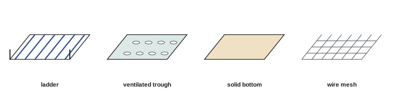
Cable trays are rigid structures that support cables, not raceways that enclose them. Common types are:
- Ladder tray: two side rails joined by rungs, with excellent ventilation and easy cable dropping between rungs. The standard choice for power cables.
- Ventilated trough tray: a bottom with openings, supporting smaller cables more continuously.
- Solid bottom tray: no openings, giving maximum support and protection, sometimes with covers, at the cost of heat dissipation (cable ampacity is reduced).
- Channel tray: a narrow single channel for a few cables or drops.
- Wire mesh (basket) tray: welded steel wire forming a light basket, popular for communications cabling in ceilings and data centres because it is easy to cut and shape on site.
Trays are made of steel (pre-galvanized, hot-dip galvanized after fabrication, or stainless for corrosive areas), aluminum (light and corrosion-resistant) or fibreglass (non-conductive and corrosion-proof). The material is chosen for strength, environment and weight.
Load and span
Each tray has a load rating: the uniformly distributed weight of cable it can carry on a given support span with a safety factor. Trays are classified by span and load, and the designer selects a class from the total weight of cables to be installed, plus allowances for future cables and any concentrated loads (such as a person standing on the tray during installation, which trays are not intended for but which happens).
In Canada, cable trays are manufactured and rated to CSA C22.2 No. 126.1, which defines load classes by span and working load, and cable tray installations follow Section 12 of the CEC, including the cable types permitted in trays and the rules for fill, spacing and bonding.
Worked problem
Checking a tray load
A ladder tray will carry twelve 3-conductor 4/0 AWG copper armoured cables weighing about 3.6 lb/ft (5.4 kg/m) each, plus control cables weighing a total of 6 lb/ft. The designer wants 25 % spare capacity for future cables. Supports will be every 12 ft. What working load is needed?
Show solution
- Power cables: 12 × 3.6 = 43.2 lb/ft.
- Total with control cables: 43.2 + 6 = 49.2 lb/ft.
- With 25 % future allowance: 49.2 × 1.25 ≈ 61.5 lb/ft (about 92 kg/m).
Answer: A tray rated for at least about 62 lb/ft on a 12-ft span is needed, so a class rated 75 or 100 lb/ft at 12 ft would be chosen. Support spacing must not exceed the span on which the rating is based; a longer span would require a stronger class.
Installing cable tray
Tray installation starts with supports: trapeze hangers (threaded rods with a strut across them), wall brackets, or centre-hung single-rod supports, spaced no farther apart than the rated span and placed near splices where the manufacturer requires (often within a quarter of the span from a splice). Straight sections are joined with splice plates bolted to the side rails; fittings (horizontal bends, tees, crosses, vertical inside and outside bends, reducers) change direction and width. Expansion splice plates are installed at intervals on long outdoor runs and at building expansion joints, with bonding jumpers across them.
Keep clear access along the tray: space above for laying cables in and for future work (commonly about 300 mm or 12 inches between stacked trays and above the top tray), and clear routes for pulling. Separate trays carrying power from those carrying communications, or use barriers within a tray where permitted, to limit interference and meet code separation rules.
Cables in tray are laid in rather than pulled where possible, using rollers and sheaves at bends to reduce friction for long pulls. On vertical runs, cables are secured to the rungs at intervals so their weight hangs on the tray rather than on the terminations; on horizontal runs, they are tied at intervals to keep them in place and maintain spacing where the ampacity calculation assumed it. Single-conductor cables of a circuit are grouped together to avoid inductive heating of the tray and unbalanced impedance.
Bonding cable tray
Metal cable tray must be bonded to ground so that any fault to the tray clears quickly. Tray sections may serve as the bonding path where they are marked and approved for that purpose and their splices provide electrical continuity, but bonding jumpers are required across expansion joints, at discontinuities and wherever sections are not mechanically bonded. Many designs also run a separate bare or green bonding conductor along the tray, attached to each section, which also serves as the bonding path for the equipment the tray feeds.
Busway
Busway (busduct) is a prefabricated assembly of copper or aluminum busbars in a protective metal housing, supplied in straight lengths and fittings that bolt together on site. It comes in two main forms:
- Feeder busway carries large currents (commonly 800 A to 5,000 A) between switchgear, transformers and switchboards, with low voltage drop and compact size compared with many parallel cables.
- Plug-in busway has openings along its length into which plug-in units (fused switches or circuit breakers in small enclosures) are inserted to tap off power. It is used in factories, where machines move, and in data centres, where overhead track busway feeds rack power distribution units and can be reconfigured without new wiring.
Installation requires care because busway joints carry the full current: sections are aligned and supported at the intervals the manufacturer specifies, joints are bolted to the specified torque (many designs use a single-bolt joint with a break-off or indicator head), and fire barriers are installed where busway passes through fire-rated walls and floors. Busway must be oriented as listed (some are listed only for horizontal runs with a particular side up), protected from water, and kept clear of sprinkler and plumbing leaks. Before energizing, the run is insulation-resistance tested, and after it carries load, joints are checked with thermography, because a poorly made joint shows as a hot spot.
Wireway
Wireway (auxiliary gutter, trough) is a sheet metal channel with a hinged or removable cover, used to collect conductors from several conduits and route them into panels, motor control centres or meter stacks, or to provide space for taps and splices. Wireways are sized for the number and size of conductors and are limited in fill and in the space taken by splices.
In Canada, Section 12 of the CEC covers wireways and auxiliary gutters, limiting the number and area of conductors they contain and the space occupied by splices and taps, and requiring that they be accessible and supported.
Wireways are installed level and plumb, with knockouts made carefully and bushings fitted, and with conductors arranged neatly and identified, because the wireway is often the place where an electrician years later has to trace circuits.
Choosing between systems
Each system suits different situations. Conduit gives the most protection and suits individual circuits and areas where cables must be enclosed. Cable tray suits many cables along a common path, especially in industrial plants, data centres and mechanical rooms, offering lower installed cost and easy additions, but it needs cable types approved for tray and leaves cables exposed. Busway suits large currents over moderate distances and loads that change position. Wireway is a local distribution aid around equipment. Large projects usually combine all four.
Cable types in tray
Not every cable may be installed in tray. Trays carry cables that are themselves robust and flame-resistant enough to be exposed: armoured and metal-clad cables, tray cables (TC and similar types) and other cables marked for use in cable tray, as well as communications cables suited to the location. Single insulated conductors are permitted in tray only in larger sizes and under specific conditions, usually in industrial settings with qualified maintenance. Ordinary building wire (such as THHN or T90) pulled loose into a tray is not acceptable; it must run in a raceway. The specification and code determine which types are permitted in each tray, and the cable jackets must be marked accordingly.
Ampacity in tray depends on how cables are arranged. Cables laid in a single layer with maintained spacing dissipate heat well, and the code allows higher ampacities for them; cables piled randomly in several layers run hotter and are derated. If the design assumed spaced cables, the installer must maintain the spacing, typically one cable diameter, with ties or spacers, rather than bunching cables together to save space.
Communications cabling in tray
Data and communications cables are usually installed in separate trays or in wire mesh tray, kept apart from power cables to limit electromagnetic interference and to meet code separation rules. They are laid in loosely, not pulled tight, because structured cabling performance depends on not deforming the cable; ties are snug but never cinched, and hook-and-loop straps are preferred. Their bend radius limits (often four times the cable diameter for balanced twisted-pair cable, more for fibre) must be respected at every transition. Where they enter rooms and racks, waterfall fittings guide them down smoothly.
Inspection and maintenance
After installation, trays, busway and wireway are inspected for supports, bonding, cable securing and labelling. In service, trays are checked periodically for overloading, damaged cables, missing covers in areas where covers are required, and accumulations of dust or debris that could insulate cables or spread fire. Busway plug-in units are checked for tightness and heating, and thermographic surveys of busway joints and tap-off connections are a standard part of preventive maintenance in data centres and plants.
Finally, plan for future additions. Cable trays are chosen partly because cables can be added later without new raceways, but only if the original installation leaves usable space, keeps cables orderly and labelled, and records the tray fill so that the next designer knows how much capacity remains. A tray filled to its limit on opening day, with unlabelled cables crossing over one another, loses most of its advantage. Labelling each cable at both ends and at intervals along long runs, and keeping a cable schedule that lists each cable's route and tray sections, makes later changes faster and safer.
Common mistakes
MistakeSpacing tray supports farther apart than the rated span.
InsteadMatch support spacing to the load class and span rating.
MistakeLeaving expansion joints without bonding jumpers.
InsteadBond across every expansion joint and discontinuity.
MistakeSeparating single conductors of the same circuit in a tray.
InsteadGroup circuit conductors together to avoid induced heating.
MistakeTorquing busway joints by feel.
InsteadTorque to the manufacturer's value and scan joints under load.
MistakeOverfilling wireways with splices.
InsteadRespect fill and splice limits; use larger wireway or junction boxes.
Summary and key terms
- Cable tray supports many cables; types include ladder, trough, solid bottom, channel and wire mesh.
- Tray load classes combine span and working load; size for cables plus future allowance.
- Install supports within the rated span, use proper fittings, and keep access space.
- Bond trays across expansion joints and discontinuities; many designs add a bonding conductor.
- Busway carries large currents; plug-in busway allows flexible tap-offs, including in data centres.
- Busway joints are torqued, tested and thermally scanned.
- Wireways collect and redistribute conductors within fill and splice limits.
- Cable tray
- An open support system for cables.
- Ladder tray
- Tray with side rails and rungs.
- Load class
- A tray rating combining span and working load.
- Splice plate
- A plate bolting two tray sections together.
- Trapeze hanger
- A strut supported on two threaded rods.
- Busway
- A prefabricated enclosed busbar system.
- Plug-in unit
- A switch or breaker that taps power from plug-in busway.
- Track busway
- Light plug-in busway used over racks in data centres.
- Wireway
- A sheet metal channel with a removable cover for conductors.
- Expansion splice
- A tray connection allowing movement, bonded with a jumper.
Practice problems
Work each problem on paper first, then reveal the answer to check.
Which tray type is standard for power cables?
Show answer
Ladder tray.
Why is wire mesh tray popular for communications cabling?
Show answer
It is light and easy to cut and shape on site.
Ten cables weigh 2.5 lb/ft each, with a 20 % future allowance. What load is needed?
Show answer
25 × 1.2 = 30 lb/ft.
What determines maximum support spacing?
Show answer
The span on which the tray's load rating is based.
How much access space is commonly left above a tray?
Show answer
About 300 mm (12 inches).
Why are cables secured on vertical tray runs?
Show answer
So their weight hangs on the tray, not on the terminations.
Where are bonding jumpers required on tray?
Show answer
Across expansion joints and discontinuities.
What is the difference between feeder and plug-in busway?
Show answer
Feeder busway carries power between equipment; plug-in busway allows taps along its length.
How are busway joints checked after energizing?
Show answer
With thermography under load.
What is a wireway used for?
Show answer
Collecting and redistributing conductors around panels and equipment.
Lesson quiz · 5 questions
Score 60% or more to complete this lesson.
Create a free account to save your progress, take quizzes and earn a certificate.