
ELEC-230 · Lesson 11 of 12 · 24 min
Panelboards, panel schedules and distribution
Every branch circuit in a commercial building starts at a panelboard, and every panelboard is fed through a chain of switchboards, feeders and often dry-type transformers. Installing this equipment correctly, making up hundreds of terminations to the right torque, balancing the load across the phases, and producing accurate panel directories are core skills of the commercial electrician. This lesson covers panelboard types and ratings, installation and working space, terminations, panel schedules and phase balancing, dry-type transformers, neutral loading, and the documentation that makes a distribution system maintainable. Feeder sizing and the code rules for overcurrent protection and transformers were covered in ELEC-220.
Panelboards
A panelboard is an assembly of busbars and overcurrent devices in a cabinet, accessible only from the front. Branch circuit panelboards (lighting and appliance panels) distribute power to lighting and receptacle circuits through small breakers, typically 15 A to 60 A; distribution panelboards feed other panels and larger loads through larger breakers or fusible switches. Each panel has a set of ratings that must suit the system:
- Voltage and system: for example 120/208 V three-phase four-wire, or the higher-voltage lighting system.
- Bus rating: the maximum continuous current the busbars carry, such as 225 A.
- Main: a main breaker, or main lugs only (MLO) when the panel is protected by an upstream device.
- Short-circuit rating: the maximum available fault current the panel and its breakers can safely withstand or interrupt, which must equal or exceed the fault current at the panel's location (ELEC-220, Lesson 4).
- Number of circuit spaces and the breaker types it accepts.
In Canada, commercial lighting panels on 600Y/347 V systems feed 347 V lighting circuits, and separate 120/208 V panels, fed through step-down transformers, serve receptacles and small equipment. Panelboards are certified to CSA C22.2 No. 29.
Installing panelboards
Panels are mounted plumb and level at the height shown on the drawings, with the top breaker handle no higher than the code maximum (about 2 m, or 6 ft 7 in, above the floor). In front of every panel there must be a clear working space, free of storage and other equipment, for safe operation and maintenance.
In Canada, Rule 2-308 of the CEC requires a minimum working space of 1 m in front of electrical equipment such as panelboards, with at least 2.2 m of headroom, and the space must not be used for storage. Rule 2-310 addresses entrances to rooms containing larger equipment.
Conduits enter the panel through knockouts in the top, bottom or sides, with locknuts, bushings and bonding where required. Gutter space inside the cabinet is limited, so conductors are trained neatly along the sides, bundled by circuit, and kept clear of the dead front. Neutral and bonding conductors land on their own bars; in panels downstream of the service, the neutral bar must be isolated from the cabinet, and the bonding bar bonded to it. The bonding jumper between neutral and ground belongs only at the service or at the secondary of a separately derived system such as a transformer.
Terminations and torque
Loose connections are a leading cause of electrical failures and fires, and over-tightened connections damage conductors and terminals. Every breaker, lug and bus connection has a specified tightening torque, printed on the equipment or in its instructions, and codes now require that connections be tightened to the specified value with a calibrated torque tool. Good practice is to strip insulation to the correct length, check that conductors are rated for the terminal temperature (usually 75 °C) and material (aluminum conductors need terminals marked for aluminum and often an anti-oxidant compound), torque each connection, and mark it with a torque stripe so that an inspector or later technician can see that it has been done and whether it has moved.
In Canada, the CEC requires that terminations be made in accordance with the equipment's certification and manufacturer's instructions, which include the specified tightening torque, and inspectors increasingly check for documented torquing.
Panel schedules
A panel schedule lists every circuit in a panel: its number, the breaker rating and number of poles, the load it serves and its location, the conductor size, and the connected load in volt-amperes on each phase. Schedules appear on the drawings (Lesson 1) and must be updated to match what is installed. The printed directory inside the panel door is the version that matters most to the people who will work on the building for decades: it must identify every circuit clearly and specifically ("Receptacles, rooms 214 and 215", not "Office") and be kept current through renovations.
In a three-phase panel, circuits are connected to phases in rotation: on a typical panel, circuits 1 and 2 are on phase A, 3 and 4 on phase B, 5 and 6 on phase C, then the pattern repeats. A two-pole breaker spans two phases, and a three-pole breaker all three. Knowing this pattern lets you calculate the load on each phase from the schedule.
Phase balancing
The loads on the three phases should be roughly equal. Unbalanced loading overloads one phase while others are lightly loaded, increases neutral current, raises losses and voltage drop on the heavy phase, and, upstream, can unbalance transformers and motors. Designers balance loads on paper, but changes during construction often upset the balance, so the installer checks the schedule against the installation and moves circuits where needed.
Worked problem
Balancing a panel
A 120/208 V three-phase panel schedule totals 14,200 VA on phase A, 9,800 VA on phase B and 11,500 VA on phase C. Find the phase currents and the imbalance, and suggest a correction.
Show solution
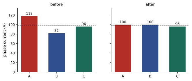
- Phase currents (each phase load divided by 120 V): A = 118 A, B = 82 A, C = 96 A.
- Average: (118 + 82 + 96) / 3 = 98.7 A. Maximum deviation: 118 − 98.7 = 19.3 A, an imbalance of about 20 %.
- Moving about 2,200 VA of single-pole circuits from phase A to phase B (for example by swapping circuit positions) gives A = 12,000 VA (100 A) and B = 12,000 VA (100 A), with C at 96 A.
Answer: After the change, the phases carry 100, 100 and 96 A, an imbalance of about 3 %. Swapping circuits means updating the schedule and directory, and checking that circuits sharing a neutral (multiwire circuits) remain on different phases.
Neutral current and harmonics
In a balanced three-phase four-wire system with purely linear loads, the phase currents cancel in the neutral and it carries almost nothing. Unbalance leaves a neutral current equal to the vector sum of the phase currents. Modern loads, such as LED drivers, computers and other electronic power supplies, also draw non-sinusoidal currents rich in the third harmonic. Third harmonic currents from the three phases do not cancel in the neutral; they add. In panels serving many electronic loads, the neutral current can approach or even exceed the phase currents, which is why designers may specify oversized (for example 200 %) neutrals for such panels and transformers rated for non-linear loads (K-rated). The installer should never reduce a specified neutral size and should not share neutrals between circuits unless the design and code allow it.
Dry-type transformers
Step-down transformers convert the building's main distribution voltage to 120/208 V for receptacles and small loads. They are typically dry-type (air-cooled), three-phase, rated from 15 to 300 kVA. Full-load currents follow from the kVA rating:
For example, a 75 kVA transformer stepping 600 V down to 120/208 V draws 75,000 / (1.732 × 600) ≈ 72 A on the primary and delivers 75,000 / (1.732 × 208) ≈ 208 A on the secondary.
Installation points: mount on vibration isolation pads (transformers hum, and vibration carries through structure), keep the ventilation clearances the nameplate requires around the enclosure, do not install in spaces that overheat, and provide the primary and secondary overcurrent protection the design and code require. The secondary of a transformer is a separately derived system, so it needs its own system bonding jumper connecting the neutral to the enclosure and the bonding conductor, and a grounding electrode conductor to the building's grounding electrode system, installed exactly as the code and drawings require. Errors here, such as missing bonding jumpers or neutral-to-ground connections made in downstream panels, create objectionable current on bonding paths and are among the most common inspection findings.
Documentation and labelling
At turnover, every panel, transformer and switchboard should carry a label identifying it, its voltage and the source that feeds it ("LP-2A, 120/208 V, fed from T-2A in electrical room 201"), along with arc flash warning labels where the study requires them. Panel directories must be complete, and the as-built panel schedules must match. These details seem small during construction, but they are what allow the owner's electricians to work safely and quickly for the life of the building.
Circuit numbering and spare capacity
Panels should leave room for growth: specifications commonly require a percentage of spare breakers and spaces (for example 20 % of the panel's capacity) and spare conduits stubbed from flush-mounted panels into accessible ceiling spaces, so that future circuits can be added without cutting walls. When assigning circuits, group related loads logically (for example lighting on the lower circuit numbers, receptacles next), keep circuits that share a neutral on adjacent positions of different phases with a handle tie or multi-pole breaker as the code requires, and avoid putting all the circuits for one critical function on one phase. Keep a record of which circuits feed which rooms during construction, because changes made in the field are easily forgotten by the time the directory is typed.
Before energizing a new panel, confirm the feeder is correctly connected (phase rotation and voltages at the main lugs), that all breakers are off, and that circuits have been tested for insulation and shorts. Energize the panel main, then circuits one at a time, checking each for correct voltage at its first device. This orderly start-up catches miswired circuits before they damage equipment or trip upstream protection.
When panels are replaced or added in existing buildings, the same principles apply with extra care: identify every existing circuit before disconnection, de-energize and lock out the feeder, photograph and label conductors, and verify the available fault current against the new equipment's rating, because utility transformers and building distribution may have changed since the original design.
Common mistakes
MistakeStoring material in the working space in front of panels.
InsteadKeep the required working space clear at all times.
MistakeTightening terminals by feel.
InsteadUse a calibrated torque tool to the specified value and mark the connection.
MistakeBonding neutral to ground in a downstream panel.
InsteadBond only at the service or at a separately derived system.
MistakeMoving circuits without updating the schedule and directory.
InsteadUpdate both whenever circuits change.
MistakeReducing a specified oversized neutral.
InsteadInstall neutrals as designed; harmonics can make neutral current very high.
Summary and key terms
- Panelboards are rated for voltage, bus current, main type, short-circuit current and spaces.
- Install plumb with handles within height limits and clear working space in front.
- Isolate neutrals in downstream panels; bond neutral to ground only at the service or a separately derived system.
- Torque every termination to the specified value with a calibrated tool and mark it.
- Panel schedules and directories must match the installation and identify circuits specifically.
- Balance phase loads; third harmonics from electronic loads add in the neutral.
- Dry-type transformers need correct protection, ventilation, isolation and system bonding.
- Panelboard
- An assembly of buses and overcurrent devices in a front-accessible cabinet.
- MLO
- Main lugs only: a panel without a main breaker.
- Short-circuit rating
- The maximum fault current equipment can safely handle.
- Working space
- The clear area required in front of electrical equipment.
- Torque stripe
- A paint mark showing a connection has been torqued.
- Panel directory
- The circuit list inside the panel door.
- Phase balancing
- Distributing loads evenly across phases.
- Triplen harmonics
- Harmonics at multiples of three times the fundamental that add in the neutral.
- Separately derived system
- A system, such as a transformer secondary, with no direct connection to the supply conductors.
- K-rated transformer
- A transformer designed for non-linear, harmonic-rich loads.
Practice problems
Work each problem on paper first, then reveal the answer to check.
What is an MLO panel?
Show answer
A panel with main lugs only, protected by an upstream device.
Why must the short-circuit rating be checked?
Show answer
It must equal or exceed the available fault current at the panel.
What working space depth is required in front of a panel in your country?
Show answer
At least 1 m (Rule 2-308).
Why mark connections with a torque stripe?
Show answer
To show the connection has been torqued and reveal any movement.
On a typical three-phase panel, which phase serves circuits 7 and 8?
Show answer
Phase A.
A phase carries 13,200 VA at 120 V. What is its current?
Show answer
110 A.
Phases carry 90, 110 and 100 A. What is the imbalance?
Show answer
Maximum deviation 10 A from the 100 A average, 10 %.
Why can neutral current be high with LED and computer loads?
Show answer
Third harmonic currents from the three phases add in the neutral.
What is the secondary current of a 45 kVA, 208 V three-phase transformer?
Show answer
45,000 / (1.732 × 208) ≈ 125 A.
Where is the system bonding jumper for a dry-type transformer installed?
Show answer
At the transformer secondary (or its first disconnect), not in downstream panels.
Lesson quiz · 5 questions
Score 60% or more to complete this lesson.
Create a free account to save your progress, take quizzes and earn a certificate.