
ELEC-230 · Lesson 1 of 12 · 25 min
Commercial electrical work and drawings
Residential wiring (ELEC-130) is mostly done with non-metallic sheathed cable, a single panel and branch circuits that an electrician can plan in a few hours. Commercial buildings, such as offices, schools, stores, hospitals, warehouses and data centres, are different in scale and in method. Conductors run in raceways that must be measured, bent and supported; distribution involves switchboards, transformers and many panelboards; lighting is designed by engineers and controlled by networks of sensors; and the work is coordinated with dozens of other trades from detailed drawings and specifications. This course covers the practical skills of commercial wiring, from bending conduit to installing lighting controls and balancing panels. This first lesson introduces commercial construction and, above all, the drawings and specifications that tell the electrician what to build.
How commercial work differs
Several features set commercial work apart from residential work:
- Wiring methods: metal and PVC raceways, armoured and metal-clad cable, cable tray, busway and wireway instead of non-metallic cable. Raceways protect conductors, allow future rewiring and are often required by building type or construction.
- Voltages and systems: three-phase four-wire systems, with higher voltages for lighting and motors and step-down transformers for receptacles (ELEC-220, Lesson 1).
- Engineered design: an electrical engineer designs the system and seals the drawings; the electrician installs to the drawings, specifications and code, and asks questions formally when something is unclear.
- Coordination: ceilings are crowded with ducts, sprinkler pipes, plumbing, structure and cable trays, and every trade needs its share of space.
- Scale and schedule: large crews, phased work, inspections at each stage, and contractual deadlines with penalties.
In Canada, commercial and industrial wiring is the work of the construction electrician (Red Seal trade 309A in most provinces), certified after an apprenticeship of about four years and an interprovincial examination. Provincial regulations define who may perform and supervise electrical work and how permits are obtained.
The construction process
A commercial project typically moves through design, bidding, construction and closeout. Electrical contractors bid on the drawings and specifications, either directly to the owner or as a subcontractor to a general contractor. Once awarded, the contractor prepares submittals (shop drawings and product data showing exactly which equipment will be supplied) for the engineer's review. During construction, questions go to the engineer as requests for information (RFIs), and changes to the scope are priced and approved as change orders. Inspections happen at rough-in, before walls and ceilings are closed, and at final. At closeout, the contractor provides as-built drawings showing what was actually installed, operation and maintenance manuals, warranties and test reports. Each of these documents has legal and financial weight: work done without an approved change order may not be paid for, and an installation that departs from the drawings without an RFI may have to be removed.
The drawing set
A commercial drawing set is organized by discipline, with a letter prefix on each sheet number: A for architectural, S for structural, M for mechanical, P for plumbing, FP for fire protection and E for electrical. The electrical drawings usually include:
- A cover sheet or legend: the symbols, abbreviations and general notes used throughout.
- Site plan: utility service, underground duct banks, site lighting, and connections to outbuildings.
- Power plans: receptacles, equipment connections, panels and circuits, floor by floor.
- Lighting plans: luminaires with their type tags, switching and control zones, and emergency lighting.
- Systems plans: fire alarm, telecommunications, security and other low-voltage systems, often by separate designers.
- Single-line diagram and riser diagrams: how power flows from the service through switchboards, transformers and panels, with ratings and feeder sizes.
- Schedules: panel schedules, luminaire schedules, equipment connection schedules and feeder schedules.
- Details: mounting heights, typical installations, grounding details, and enlarged plans of electrical rooms.
Reading the drawings
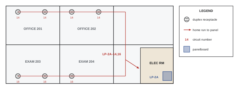
Electrical plans show the location and type of each device with symbols, but they do not show the exact route of every conduit. Lines between devices indicate circuiting, and an arrow (a home run) indicates where a circuit returns to its panel, labelled with the panel name and circuit numbers. The installer chooses the actual routing within the constraints of the specifications, the code and the space available. A few habits help:
- Read the general notes and legend first; they often contain requirements that apply everywhere, such as minimum conduit size or the requirement for a separate neutral per circuit.
- Check the scale, and confirm it against a known dimension, because drawings are often printed at a different size than they were drawn. Never scale critical dimensions; use the dimensions written on architectural plans.
- Cross-reference: a luminaire tag leads to the luminaire schedule, a panel name to its panel schedule and the single-line diagram, a detail bubble to the detail sheet.
- Compare disciplines: an electrical plan may show a receptacle exactly where the architectural plan shows a door or the mechanical plan shows a duct. Conflicts found early are cheap to resolve; conflicts found during installation are expensive.
Worked problem
Following a circuit
A power plan shows four duplex receptacles in an office tagged LP-2A-14, with a home run arrow labelled LP-2A-14,16. What does this tell you, and where do you look next?
Show solution
- The receptacles are on circuit 14 of panel LP-2A; the home run carries circuits 14 and 16 back to that panel.
- Look up LP-2A on the panel schedule to find the breaker size, the load description and the phase of circuits 14 and 16.
- Check the general notes and specification for conduit size, conductor size (often larger than the minimum to limit voltage drop on long runs) and whether a shared neutral is permitted for circuits 14 and 16.
Answer: The tag and home run give the circuit and panel; the panel schedule and specifications give the breaker, conductor and raceway requirements. Together they define what to install, while the route is left to the installer.
Specifications
The specifications (specs) are the written part of the contract documents. In both countries they are usually organized by the MasterFormat system, in which Division 26 covers electrical, Division 27 communications and Division 28 electronic safety and security. Each section has three parts: general (scope, submittals, quality requirements), products (acceptable materials and manufacturers) and execution (installation methods, testing, labelling). A Division 26 section on raceways, for example, may state that EMT is allowed only in dry interior locations above 2.4 m, that rigid metal conduit is required in exposed areas below that height, that minimum conduit size is 21 (¾ in), and that compression fittings are required in damp areas. Specifications often exceed the code minimum. Where the drawings and specifications disagree, the contract usually states which governs, and the conflict should be raised as an RFI.
Coordination and building information modelling
On modern projects, the trades coordinate their work in three-dimensional models before installation. Building information modelling (BIM) combines architectural, structural, mechanical and electrical models so that clashes, such as a cable tray running through a beam or a conduit bank colliding with a duct, can be detected and resolved on screen. Electrical contractors increasingly model their raceways, prefabricate assemblies in a shop (conduit racks, pre-bent conduit, assembled lighting whips) and deliver them to site ready to install. Prefabrication improves quality and productivity, but it depends on accurate models and on field measurements that confirm the building matches them.
Safety on commercial sites
Commercial construction sites bring hazards that are less common in houses: work at height on ladders, scaffolds and elevating work platforms; overhead work and falling objects; heavy material handling (reels of cable, lengths of rigid conduit, transformers); and energized equipment in buildings that are partly occupied or being renovated. Every site has a safety program with orientations, hazard assessments, fall protection plans and lockout procedures.
In Canada, construction safety is regulated by provincial occupational health and safety legislation and regulations for construction projects. Electrical safety in the workplace follows CSA Z462, Workplace electrical safety, which requires an energized electrical work permit and arc flash and shock risk assessment before any work on or near exposed energized parts, and lockout under CSA Z460 and the provincial rules.
The rule is simple: work de-energized, verified with a tested meter, locked and tagged. Justifications for energized work are narrow, and they never include convenience or schedule pressure.
How this course is organized
The section at the end of the lesson shows how the twelve lessons fit together.
- Lesson 1 (this lesson): commercial electrical work and drawings.
- Lesson 2: raceway systems and fittings.
- Lesson 3: conduit bending basics: stubs, back-to-backs and gain.
- Lesson 4: offsets, kicks and saddles.
- Lesson 5: advanced bending: segmented, parallel and PVC bends.
- Lesson 6: pulling conductors.
- Lesson 7: cable tray, busway and wireway.
- Lesson 8: supports, seismic restraint and firestopping.
- Lesson 9: lighting systems and layout.
- Lesson 10: lighting controls installation and commissioning.
- Lesson 11: panelboards, panel schedules and distribution.
- Lesson 12: a commercial project from estimate to inspection.
The course builds on residential wiring (ELEC-130) and complements the code requirements for commercial and industrial installations covered in ELEC-220. Bending measurements are given in inches, as they are marked on benders and used on job sites across North America, with metric equivalents where helpful.
Working with other trades
The electrician on a commercial site works alongside carpenters, drywallers, plumbers, sheet metal workers, sprinkler fitters, controls technicians, ceiling installers and many others, often in the same few square metres of ceiling space. Good relationships and early communication prevent most conflicts. Attend the foremen's coordination meetings, know the sequence in which the trades install their work (large ducts and sprinkler mains usually go in first, because they are least flexible), and claim your routes early on the coordination drawings. Respect other trades' work: do not cut through a fire-rated wall someone else has just finished, hang from their supports, or move their materials without asking. When damage or a conflict occurs, report it through the foreman rather than fixing it yourself, so the right trade does the work and the cost is assigned correctly.
Daily reports matter more than many apprentices realize. The foreman records crew size, hours, work completed, materials received, delays (for example waiting for another trade, or for an answer to an RFI) and any instructions received in the field. These records support progress payments, change order claims and, if a dispute arises, the contractor's case. A short, accurate daily report written at the end of each shift is far more valuable than a reconstruction weeks later.
Finally, commercial work rewards organization. Keep the work area clean, return unused material to the gang box, label partial reels and boxes of fittings, and keep a marked-up set of drawings current as changes happen, because those marked-up drawings become the as-builts at closeout.
Apprentices learn as much from how experienced electricians read and question drawings as from how they bend and pull. Ask why a detail is drawn the way it is, and keep notes of the answers.
Common mistakes
MistakeScaling dimensions from a printed drawing.
InsteadUse written dimensions and check the scale against a known length.
MistakeReading the electrical plans alone.
InsteadCross-reference schedules, details, specifications and other disciplines.
MistakeResolving a conflict informally in the field.
InsteadSubmit an RFI and get a written answer.
MistakeDoing extra work without a change order.
InsteadPrice and approve changes before doing them.
MistakeWorking live to keep the schedule.
InsteadDe-energize, verify, lock and tag; schedule pressure is never a justification.
Summary and key terms
- Commercial work uses raceways, three-phase systems, engineered designs and intensive coordination.
- Projects run through bidding, submittals, RFIs, change orders, inspections and closeout.
- Electrical drawings include plans, single-line and riser diagrams, schedules and details.
- Plans show devices and circuits; installers choose routes within the specifications and code.
- Specifications in Division 26 often exceed code minimums and are part of the contract.
- BIM coordination and prefabrication are increasingly common.
- Site safety covers heights, handling and energized equipment; de-energize, verify, lock and tag.
- Submittal
- Product data or shop drawings submitted for the engineer's review.
- RFI
- Request for information: a formal question to the designer.
- Change order
- An approved change to the contract scope and price.
- As-built drawings
- Drawings updated to show what was actually installed.
- Home run
- The circuit run back to the panel, shown by an arrow on plans.
- Single-line diagram
- A diagram showing the power distribution system with one line per circuit.
- Panel schedule
- A table listing each circuit in a panel with its rating and load.
- Division 26
- The MasterFormat specification division for electrical work.
- BIM
- Building information modelling: coordinated 3D models of a building.
- Prefabrication
- Assembling components in a shop before delivery to site.
Practice problems
Work each problem on paper first, then reveal the answer to check.
Name three ways commercial work differs from residential work.
Show answer
Raceway wiring methods, three-phase systems, engineered designs, coordination, scale and schedule.
What is a submittal?
Show answer
Product data or shop drawings showing what will be supplied, sent for the engineer's review.
What should you do if the drawing and specification disagree?
Show answer
Raise an RFI and follow the written answer.
What does a home run labelled LP-1B-3,5,7 indicate?
Show answer
Circuits 3, 5 and 7 run back to panel LP-1B.
Why should you not scale critical dimensions?
Show answer
Prints may be at a different size than drawn; use written dimensions.
What sheet prefix is used for electrical drawings?
Show answer
E.
What are the three parts of a specification section?
Show answer
General, products and execution.
Which MasterFormat division covers communications?
Show answer
Division 27.
What is a clash in BIM coordination?
Show answer
Two elements, such as a tray and a beam, occupying the same space in the model.
Which standard governs workplace electrical safety in your country?
Show answer
CSA Z462.
Lesson quiz · 5 questions
Score 60% or more to complete this lesson.
Create a free account to save your progress, take quizzes and earn a certificate.