
DCT-110 · Lesson 8 of 12 · 20 min
Reliability, redundancy and tiers
At the start of every shift, Dmitri Volkov, the shift lead, runs a short briefing. One line on his whiteboard never changes: current redundancy status. Most days it reads all systems at full redundancy. On the morning Jamal first notices it, it reads Hall B cooling N, one unit out for repair. Dmitri explains that Hall B is still fully cooled, but it has lost its spare: if one more cooling unit fails today, some racks will warm. Every technician on shift needs to know that, because it changes what work is allowed and what an alarm means. This lesson explains the vocabulary behind that line and the rating systems customers use to compare data centres.
Single points of failure
A single point of failure is any one component whose failure takes down the service. In an ordinary office, the main electrical panel is a single point of failure: if it fails, the whole floor goes dark. A data centre is designed to remove single points of failure from every path that matters: power, cooling and network. Where a single point of failure cannot be designed out, it is protected, watched and maintained with special care. Technicians are taught to see single points of failure everywhere: a server with both cords on one strip, a customer whose two network links run through the same tray, a rack with one cooling unit serving it.
Counting redundancy: N, N+1 and 2N
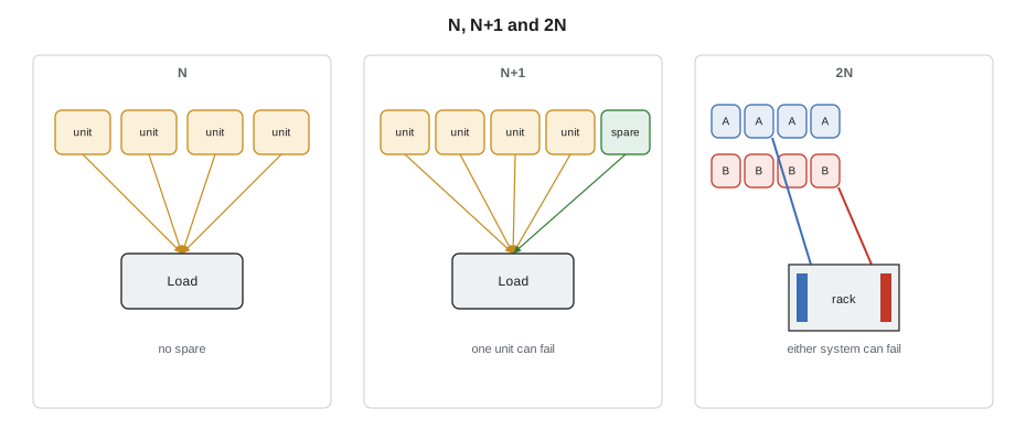
Redundancy is described by comparing the equipment installed with the equipment needed. N is the number of units needed to carry the load. If a hall needs four cooling units to stay within temperature at full load, N is four.
- N: exactly enough units, with no spare. Any failure, or any maintenance, reduces capacity below the load.
- N+1: one more unit than needed. One unit can fail, or be taken out for maintenance, and the load is still carried. Four needed, five installed.
- N+2: two spares. Common for generators and cooling units on large campuses.
- 2N: two complete, independent systems, each able to carry the whole load. An A system and a B system, each with N units. Either system can fail completely.
- 2N+1 or 2(N+1): two independent systems, each with its own spare.
Redundancy in the equipment is only half the story. Two UPS systems that feed the same switchboard are not 2N, because the switchboard is a single point of failure. True independence means separate paths all the way to the load, with no shared component that could take both down. That is why the A and B power strips in each rack, introduced in Lesson 5, matter so much: they are where two independent paths finally meet the equipment.
Concurrent maintenance and fault tolerance
Two ideas define what redundancy buys. A system is concurrently maintainable if every component that could ever need maintenance can be taken out of service, safely and on a plan, without shutting down the IT load. An N+1 cooling system with valves to isolate each unit is concurrently maintainable for cooling units; a single switchboard feeding everything is not. A system is fault tolerant if it can survive any single unplanned failure, anywhere, without the load being affected, which generally requires two fully independent paths and automatic response. Concurrent maintenance protects against planned work; fault tolerance protects against unplanned events.
Both have limits. A concurrently maintainable site that is in the middle of maintenance has lost its spare, so a second failure during the work can cause an outage. That is why Dmitri's whiteboard matters, and why maintenance windows are scheduled, announced and kept short.
Rating systems
Customers compare data centres using a few public rating systems. They differ in detail and in who certifies them, but all describe levels of redundancy and maintainability.
- Uptime Institute Tiers: four tiers. Tier I, basic capacity, has no redundant components. Tier II, redundant capacity components, adds spares but keeps a single distribution path. Tier III, concurrently maintainable, has redundant components and more than one path, so any component can be maintained without shutting down the load. Tier IV, fault tolerant, survives any single failure without affecting the load. Uptime certifies designs, constructed facilities and operations separately.
- ANSI/TIA-942: the data centre infrastructure standard from the Telecommunications Industry Association, now in its C revision published in 2024. It rates facilities as Rated-1 basic, Rated-2 redundant component, Rated-3 concurrently maintainable and Rated-4 fault tolerant, separately for architecture, electrical, mechanical and telecommunications. Auditors certify against it.
- EN 50600: the European standard series for data centre facilities, which uses availability classes 1 to 4 for power, cooling and cabling.
- BICSI 002: a data centre design best practice from BICSI, which uses availability classes F0 to F4.
| Level | Uptime Institute | TIA-942 | What it means in practice |
|---|---|---|---|
| 1 | Tier I | Rated-1 | One path, no spares; maintenance needs a shutdown |
| 2 | Tier II | Rated-2 | One path with spare components; path work needs a shutdown |
| 3 | Tier III | Rated-3 | Spares and more than one path; any part can be maintained while running |
| 4 | Tier IV | Rated-4 | Independent paths and spares; survives any single failure |
Most colocation and enterprise facilities are built to the Tier III or Rated-3 level, which balances cost and reliability. Tier IV is expensive and less common. Older material sometimes quotes availability percentages for each tier, such as 99.982 % for Tier III, but Uptime Institute stopped using those figures years ago because real availability depends so heavily on how a site is run. A Tier IV design operated carelessly can have more downtime than a Tier II design run with great discipline.
Stonebridge's halls at YUL-2 are designed to Tier III: N+1 cooling units, N+1 generators and 2N UPS and distribution to every rack. Hall D adds N+1 coolant distribution units and two coolant loops.
Calculating availability
Engineers estimate how often a system will be down by combining the availability of its parts. Components in series, where the system works only if every one works, multiply their availabilities, so a chain is weaker than its weakest link. Components in parallel, where the system works if any one of them works, are far more available than any single one. The code below shows both effects, using illustrative figures for a UPS module.
# Series and parallel availability (illustrative figures)
def series(*parts):
    a = 1.0
    for p in parts:
        a *= p
    return a

def parallel(a, n):
    # probability that at least one of n identical units is working
    return 1 - (1 - a) ** n

def k_of_n(a, k, n):
    # probability that at least k of n identical units are working
    from math import comb
    return sum(comb(n, i) * a ** i * (1 - a) ** (n - i) for i in range(k, n + 1))

hours = 8760
ups = 0.9995          # one UPS module, illustrative
switchboard = 0.99995
for name, a in [("one UPS (N)", ups),
                ("one UPS then one switchboard", series(ups, switchboard)),
                ("4 of 5 UPS modules (N+1)", k_of_n(ups, 4, 5)),
                ("two full systems (2N)", parallel(series(ups, switchboard), 2))]:
print(f"{name:30s} {a:.7f} about {hours * (1 - a) * 60:7.1f} minutes down per year")one UPS (N) 0.9995000 about 262.8 minutes down per year one UPS then one switchboard 0.9994500 about 289.1 minutes down per year 4 of 5 UPS modules (N+1) 0.9999975 about 1.3 minutes down per year two full systems (2N) 0.9999997 about 0.2 minutes down per year
The figures are illustrative, but the pattern is real. Adding a component in series always makes the system a little less available. Adding a spare in parallel makes it dramatically more available, as long as the spare is truly independent and is actually ready when it is needed. A spare that has quietly failed, or that is out for maintenance, adds nothing. That is why spares are tested, and why the redundancy status board exists.
Common-cause failures
Redundancy assumes that failures are independent: that the A side failing does not make the B side more likely to fail. Common-cause failures break that assumption. Examples include a single flood that wets both power rooms, a software bug that affects every UPS module of the same model, a contaminated fuel delivery that stops every generator, a fire that damages both paths where they run side by side, or a technician who makes the same mistake on both sides. Designers separate A and B paths physically, by fire-rated walls and different routes, partly to avoid common causes. Operators avoid them by never working on A and B at the same time, by staggering maintenance and by checking that spares are truly ready.
Redundancy and the technician
For a data centre technician, redundancy shows up as rules and habits:
- Know the current redundancy status of the hall before starting work, and treat any space running at N with extra care.
- Never work on both sides of a redundant system at the same time, and never let a task on one side disturb the other.
- Keep A and B separate at the rack: cords, strips and labels.
- Make sure customer network links that are meant to be diverse really are: different panels, different trays, different entrance rooms.
- Report anything that reduces redundancy, even if nothing has stopped working: a cooling unit in alarm, a strip that has lost power, a failed fan in a UPS.
Roz's version of the rule is that redundancy is a promise the site makes to its customers, and every technician is responsible for keeping it.
Worked problem
Is it still redundant?
A customer asks Jamal to confirm that its two network links to the internet are fully diverse. The ticket shows link 1 via carrier X from entrance room North and link 2 via carrier Y from entrance room South.
Show solution
- Check the cross-connect records: both cross-connects run from the meet-me room to the customer's cage panel.
- Check the physical routes: both run through the same overhead tray for the last 30 metres into the cage, and both terminate on the same patch panel in the same cabinet.
- Report the finding: the links are diverse from the street to the meet-me room, but share a tray, a panel and a cabinet inside the building. A single tray incident or work in that cabinet could affect both.
- Offer the options the site sells: a second patch panel in a different cabinet and a cross-connect by the alternate tray route.
Answer: True diversity has to hold for the whole path. Jamal's report lets the customer decide whether the shared section is an acceptable risk.
Testing the spares
Redundancy is only as good as the spare that has to take over. A generator that has not run for months may fail to start; a transfer switch that has not moved for a year may stick; a spare cooling unit may have a failed fan that nobody noticed because it was idle. Sites therefore test their spares on a schedule. Generators run monthly with load. Cooling units are rotated so that every unit runs regularly and none sits idle as the permanent spare. UPS batteries are tested and monitored cell by cell. At least once a year, many sites run a full test in which the utility supply is opened deliberately and the whole building runs on its generators, under a method of procedure, with every team on standby.
Technicians see these tests as scheduled changes on the shift board. During them, the site is operating with less margin than usual, so other work is limited and alarms are watched closely. A test that finds a fault is a success: it is far better to discover a generator that will not start on a calm Tuesday morning than during a storm.
Designing out human error
Designers also try to make the right action easy and the wrong one hard. Breakers and panels are labelled clearly and colour-coded by side. Covers protect emergency buttons. Interlocks stop two sources being closed onto the same bus. Monitoring screens show which systems are in maintenance. None of these replaces careful work, but each removes a chance for a mistake.
Common mistakes
MistakeAssuming two of something means redundancy.
InsteadCheck that the two paths share no component that could take both down.
MistakeTreating a site at N during maintenance as fully protected.
InsteadIt has lost its spare; avoid any risky work and watch alarms closely.
MistakeQuoting tier availability percentages as guarantees.
InsteadReal availability depends on operations; the old tier percentages are no longer used by Uptime Institute.
MistakeWorking on A and B on the same night.
InsteadStagger work so one side is always untouched.
MistakeIgnoring an alarm because nothing has failed yet.
InsteadA lost spare reduces redundancy and must be reported.
Summary and key terms
- A single point of failure is any one component whose failure takes down the service.
- N is the capacity needed; N+1 adds a spare; 2N provides two independent full systems.
- Concurrently maintainable systems allow planned maintenance without shutdown; fault-tolerant systems survive any single unplanned failure.
- Uptime Institute Tiers I to IV and TIA-942 Rated-1 to Rated-4 describe similar levels; most commercial sites are Tier III or Rated-3.
- Series components reduce availability; independent parallel spares raise it greatly.
- Common-cause failures and human error defeat redundancy; never work on both sides at once.
- Single point of failure
- A component whose failure alone takes down the service.
- N+1
- One more unit installed than the load needs.
- 2N
- Two complete, independent systems, each able to carry the whole load.
- Concurrently maintainable
- Able to have any component maintained without shutting down the load.
- Fault tolerant
- Able to survive any single unplanned failure without affecting the load.
- Common-cause failure
- One event that causes several supposedly independent components to fail together.
Practice problems
Work each problem on paper first, then reveal the answer to check.
A hall needs six cooling units and has seven. What redundancy level is that?
Show answer
N+1.
What is the difference between Tier III and Tier IV?
Show answer
Tier III is concurrently maintainable; Tier IV is fault tolerant and survives any single failure.
Why is a site running at N during maintenance at extra risk?
Show answer
It has no spare, so one more failure can affect the load.
Give one example of a common-cause failure.
Show answer
A flood in both power rooms, a fuel problem affecting all generators, or the same mistake made on both sides.
Lesson quiz · 5 questions
Score 60% or more to complete this lesson.
Create a free account to save your progress, take quizzes and earn a certificate.