
ARCH-231 · Lesson 7 of 12 · 20 min
Long-span structures
The city has asked the school for ideas for a covered rink at Kestrel Point: a roof over a full-size ice surface, open at the sides in winter so that skaters still feel the cold air, with room for spectators along one side. The clear span across the ice and the benches is 60 m. Szymańska writes the number on the board and draws beneath it the hall truss of the community hub, which spanned 22 m. 'Nearly three times the span,' she says. 'What happens to the structure?' Callum answers too quickly that it gets three times deeper. 'The moment grows with the square of the span,' Szymańska replies, 'so for the same load per metre it is about seven and a half times larger. And the weight of the structure itself grows faster still. Long spans are where structural form stops being a choice and becomes the design.'
Why long spans are different
For short spans, the dead load of the structure is a modest part of the total, and almost any reasonable system works. As spans increase, two things happen together. The bending moment grows with the square of the span, so a beam must get deeper or heavier; and the beam's own weight, which grows with its depth and size, becomes a larger and larger share of what it carries. At some span, a beam would spend all its strength carrying itself. Long-span structures avoid this trap by using form instead of mass: by spreading material far from the neutral axis in deep trusses and space frames, or by shaping the structure to follow the line of the loads, so that it works in pure compression or tension, in arches, vaults, domes, cables and membranes.
Long spans also bring problems that short spans hide. Thermal movement over 60 m is several centimetres, so supports must slide or flex. Deflection under snow can pond water on a flat roof, adding load in a vicious circle. Lateral loads on a large roof are large, and wind can lift a light roof. Erection is difficult, because the structure is not stable until it is complete, and temporary supports or lifting sequences may cost as much as the members. And the consequences of failure are severe, because long-span roofs cover crowds. The collapse of the Hartford Civic Center's space frame under snow in 1978, a few hours after a basketball game, is studied by every structural engineer: the frame's compression members buckled because of a design assumption that did not match the real connections.
Beams, girders and trusses
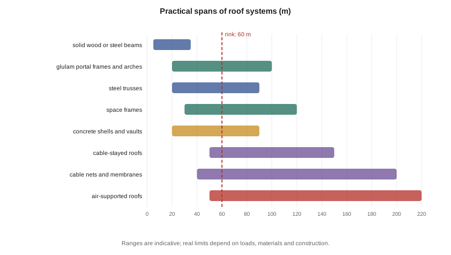
Solid beams of steel or glulam reach spans of about 30 to 40 m, with depths of about a twentieth to an eighteenth of the span. Beyond that, the web of a beam is mostly wasted material, and a truss, which concentrates material in its chords and uses diagonals only where needed, is more efficient. Flat trusses work best with depths of about a tenth to a fifteenth of the span; deeper trusses, with depths around an eighth, are lighter but need more height. Two-way systems, space frames and space trusses, are three-dimensional grids of members that spread load in both directions and need only about a twenty-fifth to a thirtieth of the span in depth, but they have many joints, and the joints set their cost.
The trade-off between depth and force is visible in the chord forces. The chords of a truss resist the bending moment as a couple, so the chord force equals the moment divided by the truss depth. A shallow truss has smaller depth and larger chord forces; a deep truss has the reverse. The script below compares the options for the rink, using a factored roof load along one frame that includes snow, roofing, purlins and the frame itself.
# Long-span roof options for a covered rink: depth, rise, sag and thrust (m, kN)
span, w = 60, 36                     # span and factored roof load along one frame (kN/m)
M = w * span ** 2 / 8
print(f"Span {span} m, load {w} kN/m: simple-span moment {M:.0f} kN m")
for name, ratio in (("flat truss", 12), ("deep truss", 8), ("space frame", 25), ("glulam beam", 18)):
    depth = span / ratio
    chord = M / depth
    print(f"   {name:<12} depth {depth:5.1f} m (span/{ratio}), chord force {chord:6.0f} kN")
for name, ratio, sign in (("arch", 6, "push"), ("cable", 10, "pull")):
    f = span / ratio
    H = w * span ** 2 / (8 * f)
    T = (H ** 2 + (w * span / 2) ** 2) ** 0.5
print(f" {name:<12} rise or sag {f:5.1f} m (span/{ratio}): thrust {H:.0f} kN ({sign}), max force {T:.0f} kN")Span 60 m, load 36 kN/m: simple-span moment 16200 kN m flat truss depth 5.0 m (span/12), chord force 3240 kN deep truss depth 7.5 m (span/8), chord force 2160 kN space frame depth 2.4 m (span/25), chord force 6750 kN glulam beam depth 3.3 m (span/18), chord force 4860 kN arch rise or sag 10.0 m (span/6): thrust 1620 kN (push), max force 1947 kN cable rise or sag 6.0 m (span/10): thrust 2700 kN (pull), max force 2908 kN
A flat truss 5 m deep carries chord forces of about 3,240 kN; a deep truss 7.5 m deep cuts that by a third; a space frame only 2.4 m deep has chord forces twice as large, spread over many members. A glulam beam of 3.3 m would be impractical. The two funicular options, an arch rising a sixth of the span and a cable sagging a tenth, carry the whole load in compression or tension with no bending at all, but each pushes or pulls on its supports with a horizontal force of 1,620 kN or 2,700 kN that the foundations or a tie must resist.
Arches and portal frames
Lesson 12 of Structures I showed that an arch shaped to the funicular line of its loads carries them in pure compression. For a roof with uniform load, the funicular is a parabola. The arch's horizontal thrust is H = wL²/8f, where f is the rise, so the thrust falls as the arch rises: an arch with a rise of a sixth of the span has a much smaller thrust than a shallow one. The thrust must be resisted, by buttresses, by heavy foundations or most simply by a tie between the springing points, buried in the floor slab or running overhead. Real roof loads are not perfectly uniform, because snow drifts and wind is uneven, so arches must also resist some bending; a hinged arch, with pins at its supports and sometimes at its crown, allows thermal movement and settlement without large stresses.
Large glulam and steel arches have roofed many arenas and exhibition halls in North America. The Richmond Olympic Oval in British Columbia, built for the 2010 Winter Olympics, spans about 100 m with composite arches of glulam and steel, carrying a roof of wood panels made from beetle-killed pine. Portal frames, rigid frames with sloping rafters, are the low-cost relative of the arch for spans of 20 to 60 m: the rigid corners take the moment that an arch would avoid by its shape, and the frame needs no tie. Most warehouses, farm buildings and arenas in small towns are portal frames of steel or glulam.
Cable-supported and cable-stayed roofs
Cables are the most efficient structural members of all, because steel strand in tension can carry very high stresses without buckling. A cable roof uses this efficiency but pays for it with large anchor forces, flexibility and sensitivity to wind uplift. Lesson 9 returns to cable nets and membranes. Cable-stayed roofs hang the roof structure from masts with straight inclined cables, like a cable-stayed bridge, so that a relatively shallow roof structure spans between cable supports. The masts can stand outside the building, which leaves the interior clear but exposes the masts and anchors to the weather and makes them a dominant architectural element.
Choosing a system
There is no single best long-span system. The choice depends on the span, the shape of the space below, the loads, the available construction methods, the budget and the architecture. Szymańska suggests a sequence of questions. Does the space want to be flat-roofed, with clear height everywhere, or can the roof rise toward the middle, as an arch, a vault or a cable would? Can the ends of the structure push or pull on the ground, or must the system be self-contained, with ties? How will it be built, and can it be erected in pieces without full scaffolding? What happens if one member fails? And what does the structure express: the precision of a truss, the gesture of an arch, the lightness of a cable?
For the rink, the students settle on three options to develop. Ingrid proposes a series of parabolic glulam arches at 6 m centres, rising 10 m, tied by steel rods buried in the concrete slab around the ice, so that the foundations carry only vertical loads. Callum proposes deep steel trusses with a flat roof, high enough at the benches for a mezzanine. Wren proposes a cable roof hung between a tall frame on the spectator side and a low concrete wall on the other, sloping like a tent toward the ice. The rest of the term will compare them; for now, Szymańska asks each student to check the one number that matters most for their scheme: the depth, the thrust or the anchor force.
Details that make long spans work
Every long-span roof needs a few special details. Expansion joints or sliding bearings let the structure move with temperature; a steel roof 60 m long expands about 25 mm for a temperature rise of 35 °C. Camber, a slight upward curve built into trusses and beams, offsets the deflection under dead load so the roof ends up flat. Roof drainage must work even with the deflected shape, and the roof must be strong enough to carry the water that collects if a drain is blocked. Lateral bracing in the plane of the roof, and bracing of compression chords against buckling, must be designed as carefully as the main members. And the connections, which in a long-span structure carry very large forces, must be designed to be built: a joint that needs a crane to hold it in place while dozens of bolts are installed is a joint that will slow the whole project.
Worked problem
Thrust of Ingrid's arches
Each of Ingrid's glulam arches spans 60 m with a rise of 10 m and carries a factored load of 36 kN/m from a 6 m width of roof. Find the horizontal thrust, the size of steel tie needed in the slab, and the reaction at each support.
Show solution
- Thrust: H = 36 × 60² ÷ (8 × 10) = 1,620 kN.
- Vertical reaction at each support: 36 × 60 ÷ 2 = 1,080 kN.
- Maximum arch force at the springing: √(1,620² + 1,080²) ≈ 1,950 kN.
- A steel tie of 350 MPa steel with a resistance factor of 0.9 needs an area of 1,620,000 ÷ (0.9 × 350) ≈ 5,140 mm², roughly an 80 mm rod or a bundle of smaller rods.
- The tie runs in the slab around the ice between the two springings, so the foundations need only resist vertical load.
Answer: Each arch thrusts about 1,620 kN, carried by a steel tie of about 5,100 mm² in the slab.
Exercise 7: long spans
- Choose one of the three rink schemes and draw its section at 1:200 with the structure at the correct depth or rise.
- Calculate the governing force for your scheme: the chord force, the arch thrust or the cable tension.
- Identify how your scheme will be erected, and what temporary supports it needs.
- Find a long-span building in your region and identify its system and span.
Self-check
- Do I know why moment grows with the square of the span?
- Can I estimate the depth of a truss or the thrust of an arch for a given span?
- Have I thought about thermal movement, ponding and erection?
Common mistakes
MistakeScaling a short-span structure up to a long span.
InsteadMoments grow with the square of the span; change the system, not just the size.
MistakeForgetting the thrust of an arch or the pull of a cable.
InsteadProvide buttresses, ties or anchors, and show them on the drawings.
MistakeDesigning a flat long-span roof without camber or drainage checks.
InsteadCamber the structure and design for ponding and blocked drains.
MistakeIgnoring the buckling of compression chords.
InsteadBrace compression chords and check the bracing as carefully as the main members.
MistakeLeaving erection to the contractor to figure out.
InsteadThink about how the structure will be built and stable at every stage.
Summary and key terms
- Long spans are dominated by self-weight, because moments grow with the square of the span.
- Beams reach about 30 to 40 m; trusses and space frames go farther by putting material where it works; depth trades against chord force.
- Arches, cables and membranes use form to carry loads in compression or tension, but need ties, buttresses or anchors for their thrust and pull.
- Portal frames and cable-stayed roofs are common, economical alternatives at intermediate spans.
- Thermal movement, ponding, bracing, connections and erection are as important as member sizes in long-span design.
- Space frame
- A three-dimensional grid of members spanning in two directions.
- Funicular
- The shape that carries a given load in pure tension or pure compression.
- Thrust
- The horizontal force an arch exerts on its supports.
- Tie
- A tension member that resists the thrust of an arch or frame.
- Camber
- An upward curve built into a member to offset its deflection.
- Ponding
- Accumulation of water in a deflected roof, which increases the load and deflection.
Practice problems
Work each problem on paper first, then reveal the answer to check.
If the span doubles and the load per unit length stays the same, how does the bending moment change?
Show answer
It becomes four times larger.
A truss carries a moment of 8,000 kN·m and is 4 m deep. What is its chord force?
Show answer
8,000 ÷ 4 = 2,000 kN.
What happens to an arch's thrust if its rise is doubled?
Show answer
It halves, because H = wL²/8f.
What caused the Hartford Civic Center roof to collapse in 1978?
Show answer
Compression members of its space frame buckled under snow, because the design assumptions did not match the real connections and bracing.
Why do long-span roofs need sliding bearings or expansion joints?
Show answer
To accommodate thermal expansion and contraction without large forces in the structure and supports.
Lesson quiz · 5 questions
Score 60% or more to complete this lesson.
Create a free account to save your progress, take quizzes and earn a certificate.