
ARCH-231 · Lesson 3 of 12 · 22 min
Frames
For the third class Szymańska brings two models made of balsa sticks and pins. The first is a square of four sticks joined at the corners with single pins. When she pushes its top sideways, it folds flat like a collapsing card table. The second is the same square, but its corners are glued solid with small gusset plates. Pushed sideways, it leans a little, its sticks curving into gentle S-shapes, and springs back when she lets go. 'The first is a mechanism,' she says. 'The second is a frame. It stands because its corners will not let the beam and the columns rotate separately. Everything about frames comes from those corners.'
What a rigid frame is
A frame is a structure of beams and columns. In a braced frame, which Structures I introduced, the joints may be simple pins and the frame is made stable by diagonal braces or by walls. In a rigid frame, also called a moment frame, the joints between beams and columns are made rigid, so that the angle between them stays the same as the frame deforms. When a rigid frame is loaded, the beams and columns bend together. The beam's ends are partly restrained by the columns, which reduces the moment at midspan, and the columns bend in response, carrying moments into the foundations.
Rigid frames have a strong appeal for architects because they leave openings free. There are no diagonals to block windows, doors and shopfronts, and no solid walls are needed for stability. A rigid frame can make a whole façade transparent, as the street front of the mixed-use building on Portage Avenue shows: its ground floor of shops is a three-bay concrete moment frame with full-height glass, while the floors above are braced by the walls around its stairs and elevators. The price of that freedom is that moment frames are more flexible than braced frames and walls, need heavier members and expensive joints, and sway more under wind.
Frames under gravity load
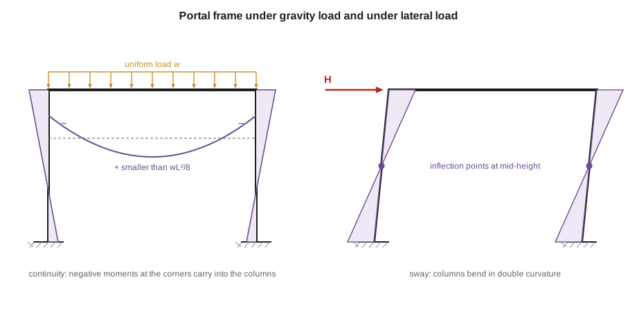
Consider a single beam on two columns, a portal frame, carrying a uniform load. If the beam simply rested on the columns on pins, it would have the familiar simple-span moment wL²/8 at midspan and none at its ends. If its ends were perfectly fixed, as if built into massive walls, it would have a moment of wL²/12 at each end, with tension on top, and only wL²/24 at midspan. A real rigid frame lies between these two cases: the columns restrain the beam's ends, but they also rotate a little, so the end moments are less than wL²/12 and the midspan moment is more than wL²/24.
Continuous beams over several supports behave in a similar way, and engineers often use moment coefficients for preliminary design: roughly wL²/10 at interior supports and wL²/16 at midspan for typical interior spans, with larger values at the end spans. The important lesson for architects is that continuity reduces the maximum moment. A continuous or framed beam can be shallower than a simple one, often by about a fifth, and its deflection is much smaller. Continuity is the reason concrete frames, which are naturally monolithic, can have relatively shallow beams.
Continuity has consequences. A framed beam has tension at the top near its supports, so its reinforcement, or its steel connection, must be designed for those negative moments. The moments carried into the columns make them bend as well as carry axial load; columns in rigid frames are therefore sized for combined compression and bending, and edge and corner columns, which receive the unbalanced moment of the beam on one side only, are usually the most heavily stressed. And because the whole frame works together, a change in one bay, such as a removed column, changes the moments in the bays around it.
Frames under lateral load
When wind or an earthquake pushes a rigid frame sideways, the frame sways, and its members bend in double curvature. Each column bends into an S-shape, with a moment of one sign at the top and the other at the bottom and a point of zero moment, a point of inflection, somewhere between. If the column bases are fixed and the beam is stiff, the inflection point sits near mid-height. The beams also bend in double curvature, with inflection points near their midspans. The resulting moments are what the joints and members must resist, and they are largest where the beams meet the columns.
Before computers, engineers analysed tall frames by hand with approximate methods based on these observations. The portal method, developed for the early steel skyscrapers, assumes that the inflection points are at the mid-height of every column and the midspan of every beam, and that the interior columns carry twice as much shear as the exterior ones, because each interior column supports two half-bays of beam. With those assumptions, the moments follow from statics alone. The portal method is still useful for sketching and checking, and Szymańska uses it to show the students where the large moments are.
# Portal method for a one-floor, three-bay moment frame along the street (m and kN)
H, h = 120, 4.5                        # factored lateral load at the roof and column height
bays = [7.5, 7.5, 7.5]               # bay widths
n_cols = len(bays) + 1
# interior columns take twice the shear of exterior columns
shares = [1] + [2] * (n_cols - 2) + [1]
unit = H / sum(shares)
print("Column shears and moments (inflection point at mid-height, fixed bases):")
for i, sh in enumerate(shares, 1):
    V = unit * sh
    print(f"   column {i}: shear {V:.1f} kN, moment top and bottom {V * h / 2:.1f} kN m")
print("Beam end moments and shears:")
for j, L in enumerate(bays, 1):
    Mb = unit * h / 2                 # beams carry the exterior column moment at each joint share
    print(f"   beam {j}: end moment {Mb:.1f} kN m, shear {2 * Mb / L:.1f} kN")
w, L = 40, 7.5                       # gravity load on the middle beam
print(f"Gravity moments in the middle beam, w = {w} kN/m over {L} m:")
print(f"   simple span       midspan {w * L ** 2 / 8:.0f} kN m")
print(f"   fixed ends        ends {w * L ** 2 / 12:.0f}, midspan {w * L ** 2 / 24:.0f} kN m")
print(f" typical frame ends {w * L ** 2 / 10:.0f}, midspan {w * L ** 2 / 16:.0f} kN m (approximate coefficients)")Column shears and moments (inflection point at mid-height, fixed bases): column 1: shear 20.0 kN, moment top and bottom 45.0 kN m column 2: shear 40.0 kN, moment top and bottom 90.0 kN m column 3: shear 40.0 kN, moment top and bottom 90.0 kN m column 4: shear 20.0 kN, moment top and bottom 45.0 kN m Beam end moments and shears: beam 1: end moment 45.0 kN m, shear 12.0 kN beam 2: end moment 45.0 kN m, shear 12.0 kN beam 3: end moment 45.0 kN m, shear 12.0 kN Gravity moments in the middle beam, w = 40 kN/m over 7.5 m: simple span midspan 281 kN m fixed ends ends 188, midspan 94 kN m typical frame ends 225, midspan 141 kN m (approximate coefficients)
For the shopfront frame, with a factored lateral load of 120 kN at the second floor, each interior column takes a shear of 40 kN and a moment of 90 kN·m at its top and bottom, and each exterior column half as much. The beams have end moments of 45 kN·m. The script also shows the effect of continuity on gravity moments: the middle beam, which would have 281 kN·m at midspan as a simple span, has about half that at midspan as part of the frame, with larger moments at its ends. Under combined gravity and wind, the end moments add on one side of each joint and subtract on the other, and the designer must check both cases.
Stiffness and drift
Moment frames are flexible, so their design is often governed by how much they sway rather than by strength. The sideways movement of one floor relative to the one below is called interstorey drift, usually expressed as a fraction of the storey height. Codes limit drift under earthquake loads, and designers limit drift under wind to protect cladding, partitions and the comfort of occupants. A common target for wind is a drift of no more than about 1/400 to 1/500 of the storey height. Too much drift cracks drywall, breaks windows and makes elevators bind; in tall buildings, sway can also make people seasick.
Drift depends on the stiffness of the beams and the columns together. A frame with deep, stiff beams and slender columns sways mostly by bending of the columns; a frame with stiff columns and shallow beams sways mostly by bending of the beams. To limit drift, the designer increases the members that are most flexible, often the beams, since a deeper beam is cheap compared with a larger column. Frames with fixed bases sway far less than frames with pinned bases, because pinned bases double the moment at the top of the column, but fixed bases need large foundations to resist the column moments. For a building of more than a few storeys, moment frames alone become heavy, and they are combined with braced cores or walls, which Lesson 5 explains.
Joints
The rigid joint is the heart of a moment frame, and the place where most of its cost lies. In reinforced concrete, joints are naturally monolithic, but the reinforcing bars of beams and columns crossing in every direction make them congested, and in earthquake regions they need closely spaced ties to keep the concrete core intact. In steel, a moment connection must transfer the beam's flange forces into the column: the flanges are welded with full-penetration welds to the column, or bolted through end plates, and the column often needs stiffener plates across its web where the beam flanges arrive. A steel moment connection can cost several times as much as a simple shear connection, so engineers use as few as they can, concentrating them in a few frames on the building's perimeter and connecting the rest of the beams simply.
Wood rarely forms good rigid joints, because the fasteners slip and the wood around them splits under the large forces that moment connections require. Glued-in steel rods, steel knife plates and special connectors can make moment joints in glulam, as in the portal frames of some arenas and barns, but for most timber buildings, lateral stability comes from braces or shear walls. Szymańska tells the students that the honest way to express a frame is to show its corners: a deep haunch where beam meets column, a thickened joint or a visible plate tells the observer where the frame's strength lies.
Frames as architecture
Great buildings have made the rigid frame their subject. Mies van der Rohe's Crown Hall, completed in 1956 at the Illinois Institute of Technology, hangs its roof from four deep steel plate girders that stand above it, so the hall below is a single column-free space framed in glass. Industrial portal frames, the simple sheds of steel or concrete that house warehouses and factories, are rigid frames reduced to their essentials. Many concrete buildings of the 1950s and 1960s expressed their moment frames as a grid of columns and spandrel beams on the façade. Szymańska's point is that the frame is a choice with spatial consequences: it frees the walls but fixes the grid, and it needs depth in its beams and corners to work.
Worked problem
A shopfront frame with pinned bases
The shopfront frame has three bays and four columns 4.5 m tall, with a factored lateral load of 120 kN at the top. The engineer is considering pinned column bases to reduce the cost of the foundations. Estimate the column moments with pinned bases and compare them with fixed bases.
Show solution
- Shears are shared as before: exterior columns 20 kN, interior columns 40 kN.
- With pinned bases the moment at the base is zero, and the inflection point moves to the base.
- The column moment at the top is then the full shear times the height: interior 40 × 4.5 = 180 kN·m, exterior 90 kN·m.
- With fixed bases the top moment was half of this, 90 kN·m for an interior column.
- The beams must also carry twice the moment at the joints, and the frame will sway roughly four times as much for the same members.
- Pinned bases save on foundations but cost in columns, beams and stiffness.
Answer: Pinned bases double the column and beam moments at the top joints; the engineer will weigh that against the cost of fixed bases.
Exercise 3: frames
- Build two balsa portal frames, one with pinned corners and diagonals, one with rigid corners, and compare how they deform.
- Draw the moment diagram for a three-bay portal frame under gravity load and under wind, and mark the inflection points.
- Identify the parts of your studio project where a moment frame would free a façade or a ground floor.
- Sketch a corner of a steel or concrete moment frame and show how you would express it.
Self-check
- Can I explain why a rigid frame stands without bracing?
- Do I know where the largest moments occur in a frame under wind?
- Do I understand why moment frames are often governed by drift?
Common mistakes
MistakeAssuming a frame with pinned joints is stable.
InsteadWithout rigid joints, braces or walls, a frame of pinned members is a mechanism.
MistakeSizing framed beams for the simple-span moment only.
InsteadContinuity creates negative moments at the supports; design both regions.
MistakeIgnoring the bending in frame columns.
InsteadColumns in rigid frames carry moments as well as axial loads, especially at edges and corners.
MistakeUsing moment frames everywhere in a steel building.
InsteadMoment connections are costly; use a few frames and connect the other beams simply.
MistakeChecking strength but not drift.
InsteadFrames are flexible; check sway under wind and earthquake.
Summary and key terms
- A rigid or moment frame resists load through rigid beam-column joints that make beams and columns bend together.
- Under gravity, continuity reduces midspan moments and creates negative moments at the supports and in the columns.
- Under lateral load, members bend in double curvature with inflection points near mid-height and midspan; the portal method uses this for quick analysis.
- Moment frames keep façades open but are flexible; drift often governs their design.
- Joints are the costly heart of a frame: congested in concrete, welded or bolted with stiffeners in steel, difficult in wood.
- Rigid frame
- A frame whose beam-column joints resist rotation, also called a moment frame.
- Portal frame
- A single bay of two columns and a beam with rigid joints.
- Point of inflection
- A point in a member where the bending moment changes sign and is zero.
- Portal method
- An approximate method for analysing frames under lateral load.
- Drift
- The sideways movement of one floor relative to the floor below, usually given as a fraction of the floor height.
- Moment connection
- A joint that transfers bending moment between beam and column.
Practice problems
Work each problem on paper first, then reveal the answer to check.
A beam of span 8 m carries 30 kN/m. Compare its simple-span moment with the end moment if fully fixed.
Show answer
Simple: 30 × 64 ÷ 8 = 240 kN·m; fixed end: 30 × 64 ÷ 12 = 160 kN·m.
In the portal method, why do interior columns carry twice the shear of exterior ones?
Show answer
Each interior column supports two half-bays of beam, the exterior columns only one.
A column 4 m tall with a fixed base carries a shear of 25 kN. What are its end moments by the portal method?
Show answer
25 × 4 ÷ 2 = 50 kN·m at the top and at the bottom.
What drift limit might a designer use under wind for a storey 3.5 m tall?
Show answer
About 1/400: 3,500 ÷ 400 ≈ 9 mm.
Why are wood moment frames uncommon?
Show answer
Fasteners slip and wood splits under the large forces at moment joints, so wood buildings are usually braced instead.
Lesson quiz · 5 questions
Score 60% or more to complete this lesson.
Create a free account to save your progress, take quizzes and earn a certificate.