
ARCH-231 · Lesson 12 of 12 · 22 min
Structural design project
The last weeks of the course bring the term's threads together. Each student prepares a structural design for their housing studio project and presents it to a review panel: Szymańska, Priya Anand from Lesson 11, and Professor Castellanos from the housing studio, who wants to know whether the structure will change her students' plans. The brief is short. Choose a structural system and justify it against alternatives; draw the gravity and lateral systems on every floor; size the main members and foundations well enough to draw them at the right depth; show how the services fit; and explain the structure's effect on the architecture. This lesson follows Wren's project, the Greenway Homes scheme that has appeared throughout the course, and the questions the panel asks.
The building
Greenway Homes is a U-shaped block of 49 homes around a courtyard open to the south, on the old lumber yard across the greenway from the community hub. The north bar is 44 by 11 m, four floors with a single-loaded corridor along the greenway; the east bar is 28 by 17 m, four floors with a double-loaded corridor; and stacked townhouses on the west are three floors. A shared corner core with a stair and elevator joins the north and east bars, and there are stairs at the far ends of both bars. The site sits on the deep clay of the area, and the geotechnical report recommends piles. The housing studio fixed the budget, the height limit of 15 m and the clear heights; Wren's task is to find the structure that fits all three.
Choosing the system
Wren compares three systems for the two bars: light wood frame, the platform construction of studs, joists and sheathing used for most North American housing of up to six floors; mass timber, with CLT floors and walls or a glulam frame, as tested in Lesson 10; and a concrete flat plate, as sized in Lesson 2. She scores each against six criteria with weights agreed with the housing studio: cost, carbon, construction schedule, acoustics, floor depth and fire. Her scores are judgements, but writing them down makes the argument visible and lets the panel challenge it.
# Comparing three structural schemes for Greenway Homes (scores 1 to 5, higher is better)
criteria = {"cost": 0.30, "carbon": 0.20, "schedule": 0.15, "acoustics": 0.15, "floor depth": 0.10, "fire": 0.10}
schemes = {
    "light wood frame": {"cost": 5, "carbon": 4, "schedule": 3, "acoustics": 3, "floor depth": 4, "fire": 3},
    "mass timber":      {"cost": 3, "carbon": 5, "schedule": 5, "acoustics": 3, "floor depth": 4, "fire": 4},
    "concrete flat plate": {"cost": 2, "carbon": 2, "schedule": 3, "acoustics": 5, "floor depth": 5, "fire": 5},
}
def score(s, wts):
    return sum(wts[k] * s[k] for k in wts)
for name, s in schemes.items():
    print(f"{name:<20} weighted score {score(s, criteria):.2f}")
alt = dict(criteria, cost=0.15, carbon=0.35)
print("If carbon matters more than cost:")
for name, s in schemes.items():
    print(f"   {name:<20} {score(s, alt):.2f}")
# rough quantities for the east bar: area, structural weight and embodied carbon (m2 of floor)
area = 1900
for name, wt, co2 in [('light wood frame', 150, 60), ('mass timber', 250, 90), ('concrete flat plate', 800, 220)]:
print(f"{name:<20} structure about {area * wt / 1000:,.0f} t, embodied carbon about {area * co2 / 1000:,.0f} t CO2e")light wood frame weighted score 3.90 mass timber weighted score 3.90 concrete flat plate weighted score 3.20 If carbon matters more than cost: light wood frame 3.75 mass timber 4.20 concrete flat plate 3.20 light wood frame structure about 285 t, embodied carbon about 114 t CO2e mass timber structure about 475 t, embodied carbon about 171 t CO2e concrete flat plate structure about 1,520 t, embodied carbon about 418 t CO2e
With cost weighted most heavily, light wood frame and mass timber tie, and concrete trails. If carbon is weighted more than cost, mass timber leads. The rough quantities make the trade-offs concrete: the concrete flat plate would weigh about five times as much as the wood frame, with about four times the embodied carbon, and its weight would roughly double the number of piles. Wren chooses light wood frame for the homes, because Greenway's budget is tight and the scheme is well within the height limit for wood frame construction, with mass timber for the common room at the corner, where an exposed CLT ceiling and glulam beams give the room its character. Anand notes that the tie is useful information in itself: it tells Greenway that a mass timber scheme would not be out of reach if a grant for low-carbon construction became available.
The gravity system
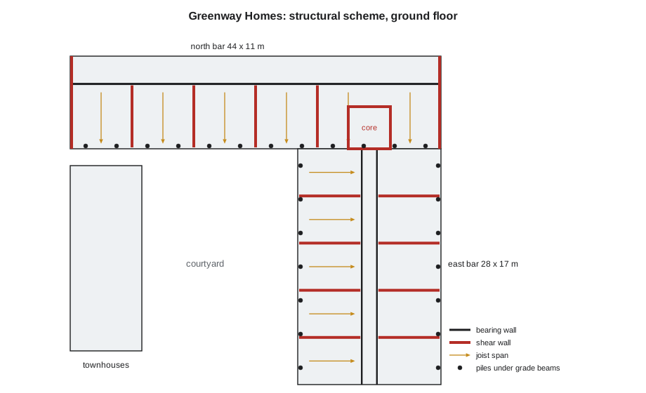
In the light wood frame scheme, the floors are prefabricated wood floor trusses or I-joists spanning between bearing walls. Wren aligns the structure with the plan: in the east bar, the party walls between homes run across the bar at about 6.6 m centres and the corridor walls run along it. The floor joists span the shorter distance, from the exterior walls to the corridor walls, about 7.2 m on each side, and the corridor ceiling hangs from short joists across the corridor. In the north bar, with its single-loaded corridor, the joists span from the courtyard wall to the corridor wall. All bearing walls stack from the roof to the ground floor, which Szymańska's light-table check in Structures I confirmed: the only transfers are at the ground floor of the east bar, where the lobby and common room open up the plan, and these are carried on glulam beams and steel columns.
The party walls are double stud walls, two separate rows of studs with a gap between them, which give the sound separation needed between homes and the fire separation required by the code; each row carries the floor on its own side. The floor build-up is a 38 mm gypsum-based topping over the subfloor, for sound and fire, with resilient channels under the joists carrying the ceiling. Wren calculates the floor zone at about 450 mm for the trusses, topping and ceiling, so the four floors of homes with 2.6 m clear height fit comfortably within the height limit, with room for a roof of sloped trusses over the north bar.
The lateral system
For lateral loads, Wren uses the walls she already has. Across the east bar, the party walls act as shear walls for wind on the long face, as Lesson 5 calculated: six lengths of 6 m, with edge nailing at 75 mm at the ground floor and hold-downs or continuous rods at their ends. Along the bar, the corridor walls, with their door openings, are weaker, so she adds the solid exterior walls at the ends of the bar and the walls of the core. In the north bar, the end walls and the party walls across the bar resist wind from the north and south, and the long courtyard and corridor walls, with sections of solid wall between windows, resist wind from the east and west. The floors are wood diaphragms, with blocking and nailing designed by the engineer, chords at their edges and collectors at the core.
The corner of the U, where the two bars meet, needs special thought. In a low-seismic region, the bars can be tied together through the core, which acts as a strong point for both wings, as Lesson 4 suggested. The engineer will design the diaphragm connections at the corner for the forces between the wings, and the expansion and shrinkage of the long wood bars will be accommodated by gaps at their far ends. The panel asks why Wren did not separate the wings with a joint, as she would in Vancouver. Her answer is that a joint would need two walls side by side at the corner, a doubled core and a joint through every finish, while the low seismic forces in Winnipeg do not demand it. Anand agrees.
Shrinkage, fire and acoustics
Light wood frame buildings of four floors shrink measurably as the lumber dries after construction, mostly in the horizontal plates and floor joists, where the wood is loaded across its grain. Wren estimates the shrinkage of each floor at about 6 to 10 mm, accumulating to about 25 to 40 mm at the roof. Elements that do not shrink must accommodate this movement: the elevator shaft and its rails, the brick base and the plumbing stacks, which pass through all four floors. The engineer specifies continuous tie rods with shrinkage compensators for the shear walls, and the architects design slip joints where the brick meets the siding and where the stair and elevator meet the floors.
The code's limits for wood frame buildings of this height require sprinklers, fire-rated separations between homes and between floors, and noncombustible or fire-retardant treated construction in some places. Wren's floors and walls use tested assemblies: layers of fire-rated gypsum board, insulation and resilient channels that also provide the required sound transmission ratings. The common room's exposed CLT ceiling is sized with extra thickness for its char layer, as in Lesson 10.
Foundations and the ground floor
The building stands on piles through the clay to the till, with pile caps under the corners and points of heavy load and grade beams spanning between the caps under every bearing wall. Because the walls carry relatively light loads, the piles are modest: cast-in-place concrete piles of about 400 mm diameter, at 3 to 4 m centres under the walls. The ground floor is a structural slab on void forms, suspended above the swelling clay and spanning between the grade beams, with a vapour barrier and insulation below. The heavy elements, the core and the transfer columns at the lobby, sit on larger pile groups. Wren's quick takedown, using the methods of Structures I, gives the pile counts, and the geotechnical report's pile capacities complete them.
The review
The panel's questions follow Lesson 11's pattern. Where are the columns? In this scheme the walls are the structure, and Wren shows they stack. Where is the lateral system? In red on every floor plan, in both directions, with the unit shears and hold-down forces from Lesson 5. Where are the holes? Wren's section at 1:20 shows the ducts from the in-suite ventilation units running in the corridor ceiling between the joists, which are open-web trusses that let ducts pass through them, and the plumbing stacks aligned in a column of bathrooms from floor to floor. Castellanos asks whether the structure changed the plans. It did in two places: the lobby gained a pair of glulam beams and steel columns where Wren had wanted a wall-free space, and the homes at the south end of the east bar lost a corner window to keep a length of shear wall. Wren thinks the trade is worth it, and says so.
Szymańska's closing comment is about the whole course. 'Two terms ago, you drew walls and columns because the plan needed them. Now you know what they do: which ones carry gravity, which ones carry wind, which ones you can cut and which ones you cannot. Your engineers will check every number you have calculated, and they should. But you will draw buildings that stand, and you will know why.'
The other projects
The other students present different strategies. Callum, whose housing scheme has a ground floor of shops under three floors of homes, proposes a concrete podium with a flat plate at the second floor, carrying wood frame above, and spends much of his presentation on the transfer at the podium, where the shop grid meets the party walls. Ingrid uses CLT walls and floors throughout, as a panel system, with the walls as both bearing and shear walls, and argues that the factory precision justifies the cost. Joon-ho proposes a steel frame with long spans, to leave the homes free to be reconfigured, and the panel challenges him on fire protection, acoustics and the floor-to-floor height that his deep beams need. Each scheme has a reasoned case, and none is wrong; the panel's job is to test the reasoning.
Worked problem
Hold-down at the corner window
At the south end of the east bar, the party wall at the corner home acts as a shear wall 6 m long. The housing studio wanted to cut a window 1.5 m wide into its ground-floor end. With the overturning moment from Lesson 5, about 518 kN·m per wall at the ground floor, what happens to the hold-down force if the wall is shortened to 4.5 m?
Show solution
- Resisting moment from dead load scales roughly with the square of the length: 288 × (4.5 ÷ 6)² = 162 kN·m.
- The overturning moment stays about the same if the wall still takes its share of the shear: 518 kN·m.
- Hold-down force: (518 − 162) ÷ 4.5 = 79 kN, compared with 38 kN for the full wall.
- The unit shear also rises by a third, from 12.4 to 16.5 kN/m, which needs tighter nailing or sheathing on both sides.
- Wren keeps the full wall and moves the window to the adjacent wall, which is not a shear wall.
Answer: Shortening the wall would double the hold-down force or more and raise the unit shear by a third, so the window moves.
Exercise 12: structural design project
- Choose a structural system for your housing studio project and justify it against two alternatives with a weighted comparison.
- Draw the gravity system on every floor, with bearing walls or columns, beams and the span direction of every floor.
- Draw the lateral system on every floor in both directions, with the unit shear in the ground-floor walls.
- Size the main members and foundations, and draw a section showing structure, services and floor build-up at 1:20.
- Present the scheme in ten minutes, and list three changes the structure made to your plans.
Self-check
- Can I explain why I chose my system, with evidence?
- Does every load have a path to the ground, in gravity and in both lateral directions?
- Have I drawn the structure at its real depth and coordinated the services?
Common mistakes
MistakeChoosing a system because it is fashionable.
InsteadCompare systems against criteria that matter to the client, and write the comparison down.
MistakeDrawing the lateral system on one floor only.
InsteadShow it on every floor, stacked and continuous, in both directions.
MistakeCutting openings in shear walls late in design.
InsteadCheck with the engineer and move openings to walls that are not resisting the governing shear.
MistakeForgetting shrinkage in wood frame buildings.
InsteadAllow for movement at elevators, brick, stairs and plumbing stacks.
MistakePresenting a structure without saying how it changed the architecture.
InsteadExplain the trade-offs, and show that they were worth making.
Summary and key terms
- A structural design starts with a reasoned choice of system, compared with alternatives against criteria agreed with the client.
- The gravity system aligns bearing walls or columns from roof to foundation and spans floors in their efficient direction.
- The lateral system uses walls or frames in both directions, continuous and balanced, with diaphragms tying it together.
- Shrinkage, fire, acoustics, foundations and services shape the details of every structural scheme.
- A good presentation answers the engineer's three questions: where are the columns, where is the lateral system and where are the holes.
- Platform framing
- Light wood construction in which each floor is built as a platform for the walls above.
- Double stud wall
- Two separate rows of studs with a gap, used between homes for sound and fire separation.
- Shrinkage compensator
- A device that keeps a tie rod tight as wood framing shrinks.
- Grade beam
- A beam at ground level that spans between pile caps and carries walls.
- Weighted comparison
- A table of scores multiplied by agreed weights to compare options.
- Transfer
- A beam or element that carries a wall or column that does not continue below.
Practice problems
Work each problem on paper first, then reveal the answer to check.
Why do light wood frame buildings shrink mostly in their plates and joists?
Show answer
Wood shrinks most across the grain, and plates and joists are loaded across the grain, while studs shrink little along their length.
A comparison gives scores of 4 and 3 on a criterion with a weight of 0.3. What is the difference in weighted score?
Show answer
0.3 × (4 − 3) = 0.3.
Why does Wren tie the two wings together through the core rather than separating them?
Show answer
Seismic forces are low, so a joint is not required, and tying them avoids doubled walls and joints through every finish.
What happens to the hold-down force when a shear wall is shortened?
Show answer
It increases, because the overturning moment stays similar while the lever arm and resisting dead load decrease.
Name three things a structural section at 1:20 should show.
Show answer
The structure at its real depth, the services that run through or below it, and the ceiling and floor build-up.
Lesson quiz · 5 questions
Score 60% or more to complete this lesson.
Create a free account to save your progress, take quizzes and earn a certificate.