
ARCH-231 · Lesson 5 of 12 · 22 min
Lateral systems: braced frames, moment frames and shear walls
Szymańska opens the fifth class by setting a shoebox on the table with its lid removed and both ends cut out. She pushes its top along the long side; it shears into a parallelogram almost at once. Then she tapes a strip of card diagonally across one side and pushes again; the box resists. She tapes a solid card over the other side, and the box resists even more. Finally she pushes the box along the short direction, where nothing has been added, and it collapses again. 'Lesson 4 told you how big the push is,' she says. 'This lesson is about what pushes back. You need something in every direction, and enough of it, in the right places.'
The three vertical systems
A building resists lateral loads with vertical elements of three main kinds, which can be used alone or combined. Braced frames add diagonal members to a frame of beams and columns, turning each braced bay into a vertical truss: the diagonals carry the lateral load as tension or compression, and the columns carry the overturning as axial forces. Moment frames, described in Lesson 3, resist through rigid joints and bending of beams and columns. Shear walls are solid walls of concrete, masonry or sheathed wood or steel framing, which act as deep vertical cantilevers fixed at the foundation, carrying lateral load in shear along their length and overturning as tension and compression at their ends.
The three systems differ in stiffness, cost and their effect on the plan. Shear walls are the stiffest, and a few walls of concrete or masonry around stairs and elevators can brace a building of twenty or thirty floors. They are also the least flexible architecturally, because they are solid. Braced frames are nearly as stiff for their weight and use less material, but the diagonals cross windows and doors; they suit cores, end walls and industrial buildings, and they have often been expressed on the façade, as on the John Hancock Center in Chicago. Moment frames are the most open and the most flexible, and the most expensive per unit of stiffness.
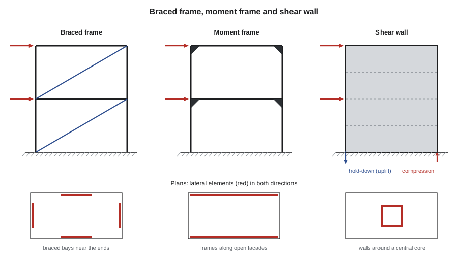
Braced frames
The simplest braced frame is a single diagonal in a bay. It carries the lateral load as tension when the load comes one way and compression when it comes the other, so it must be designed for buckling as well as tension. An X-brace, two diagonals crossing, can be designed so that only the tension diagonal works at any moment and the other is allowed to buckle harmlessly; this permits slender rods or cables, as in the hub's braced bays in Structures I. Chevron or inverted-V braces meet at the middle of the beam above, leaving room for a door or corridor under the beam; eccentric braces deliberately offset the diagonals so that a short link of the beam yields in a large earthquake, combining stiffness with ductility.
The forces in braces follow from statics. In a single braced bay of width b and height h, the horizontal component of the brace force equals the storey shear the bay carries, so the brace force is the shear divided by the cosine of the brace's angle to the horizontal. Flat braces carry more force than steep ones for the same shear, and very steep braces make the columns work harder. Braces at about 35 to 55 degrees are most efficient. The columns at the ends of a braced bay carry the overturning moment as a couple: compression at one end and tension at the other, equal to the moment divided by the bay width, accumulating floor by floor down to the foundation.
Braced frames need continuity from roof to foundation. A brace that stops at a floor and resumes in a different bay above transfers its force through the floor diaphragm, which must be designed for it. Braced bays should be stacked in the same plan location on every floor wherever possible, and placed so that the building's centre of resistance coincides with the centre of the lateral load, or the building will twist.
Moment frames in the lateral system
Moment frames earn their place where openness matters: shopfronts, lobbies, long glazed façades and floors where braces or walls would interfere with use. In a tall building they are usually combined with a core: the moment frames on the perimeter and the braced or walled core inside share the lateral load according to their stiffness. Because the core is much stiffer, it takes most of the load, and the frames contribute mainly to resisting twist. In steel buildings, perimeter moment frames were the basis of the framed tube, used for very tall buildings from the 1960s: closely spaced columns and deep spandrel beams around the perimeter made the whole façade act as a hollow tube, as in the twin towers of the World Trade Center in New York.
Shear walls
A shear wall acts as a vertical cantilever. Lateral load at each floor is carried down the wall, which resists it in two ways. Along its length, the wall carries shear: the force per unit length of wall, called the unit shear, is the storey shear divided by the total length of walls resisting it. And as a whole, the wall resists the overturning moment, the lateral forces times their heights, as a couple between its two ends: compression at one end, tension at the other. Long walls carry overturning easily; short, tall walls are hard to hold down. Openings for doors and windows divide a wall into shorter segments, and the segments between openings, called piers, act as separate shorter walls.
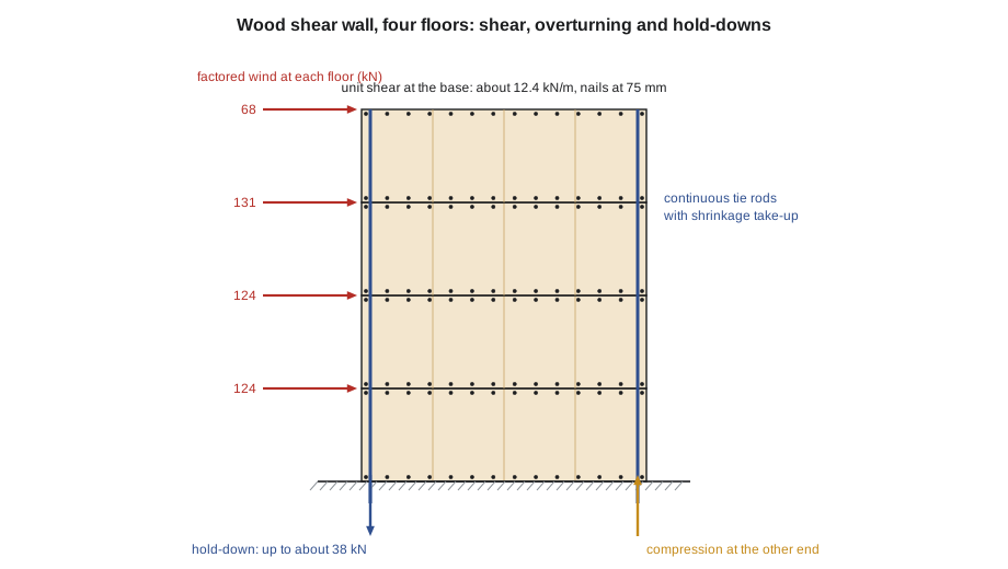
Concrete and reinforced masonry shear walls are common around the stair and elevator cores of concrete and steel buildings. In wood buildings, the shear walls are the exterior and interior walls themselves, framed with studs and sheathed with plywood or OSB nailed to the studs at close spacing along the panel edges. The nails carry the shear between the sheathing and the framing, and their spacing and size set the wall's capacity. At each end of a wood shear wall, a hold-down anchor ties the end studs to the floor or foundation below, resisting the uplift from overturning. In a four-floor wood building, these anchors are often continuous rods running from the roof to the foundation, with take-up devices that tighten as the wood shrinks.
# Wood shear walls for the east bar of Greenway Homes, wind along the long face (kN, m)
V_level = [67.8, 130.6, 124.2, 124.0]        # factored wind force at levels 4 (roof), 3, 2 and 1
fh = 3.0                                # floor-to-floor height
walls = 6                           # number of shear walls in this direction
Lwall = 6.0                           # length of each wall
dead_line = 4.0                          # factored resisting dead load on the wall (kN/m), at the low 0.9 factor
capacity = [('150 mm', 7.0), ('100 mm', 10.0), ('75 mm', 12.5), ('50 mm', 16.0)]   # kN/m                          # illustrative factored resistances for one side of OSB, by edge nail spacing
V = 0.0; M = 0.0
print("Level  shear   unit shear   nailing           overturning   hold-down")
for k, F in enumerate(V_level):
    level = 4 - k
    M += V * fh                            # moment from the shear above, over this floor height
    V += F
    M_here = M + V * fh                    # overturning moment at the base of this floor
    v = V / (walls * Lwall)                # unit shear along the walls
    nail = next((n for n, c in capacity if c >= v), 'needs a second sheathed side')
    resist = dead_line * Lwall ** 2 / 2 * (k + 1)   # dead load from the floors and roof above this level
    T = max(0.0, (M_here / walls - resist) / Lwall)
print(f" {level} {V:6.1f} {v:6.1f} kN/m {str(nail):<16} {M_here / walls:8.0f} kN m {T:6.1f} kN")Level shear unit shear nailing overturning hold-down 4 67.8 1.9 kN/m 150 mm 34 kN m 0.0 kN 3 198.4 5.5 kN/m 150 mm 133 kN m 0.0 kN 2 322.6 9.0 kN/m 100 mm 294 kN m 13.1 kN 1 446.6 12.4 kN/m 75 mm 518 kN m 38.3 kN
For the east bar of Greenway Homes, the walls across the bar between homes resist wind on the long face. Wren counts six usable lengths of 6 m each, broken at the central corridor. At the top floor the unit shear is small, and the lightest standard nailing is enough; at the ground floor, with the whole building's wind load accumulated, the unit shear reaches about 12.4 kN/m and the nails must be at 75 mm spacing along the panel edges. The resistances in the script are illustrative values for the exercise; the engineer will use the tables of CSA O86. The overturning shows the same pattern. In the upper floors, the weight of the walls and floors holds the ends of the walls down; in the lower floors, uplift exceeds the dead load and the hold-downs must take up to about 38 kN at each wall end.
Joon-ho points out that the ground floor needs the most nails and the strongest anchors, and that the ground floor is also where the architects want the most openings, for the lobby, common room and entrances on Aldous Street. Szymańska nods. 'That is the shear wall's eternal conflict. The fix is to keep long, solid walls where the shear is highest, and to put the generous openings where the walls are not working: at the ends of the bar, and in the walls running the other way, which carry the wind on the short face.'
Diaphragms and the layout of the system
The vertical elements only work if the floors and roof deliver load to them. Lesson 9 of Structures I described floors and roofs as diaphragms, horizontal beams that collect lateral load from the walls and carry it to the braced frames or shear walls. A diaphragm can be flexible, like a plywood floor spanning between widely spaced shear walls, in which case each wall carries the load from its own tributary width; or rigid, like a concrete slab, in which case the load is shared in proportion to the walls' stiffness. In both cases, the diaphragm needs chords at its edges and collectors to drag load into walls that are shorter than the diaphragm's edge.
A good lateral layout has four qualities. It has resistance in both principal directions. It distributes that resistance so the building does not twist: walls or braced bays near the perimeter, or at least balanced about the centre of mass. It is continuous, with walls and braces stacked from roof to foundation. And it is redundant, with more than one line of resistance in each direction, so that the failure of one element does not leave the building without support. Szymańska asks the students to draw a plan of each floor of their studio project with the lateral elements in red, and to check each of these four qualities.
Combining systems
Most buildings combine systems. The mixed-use building on Portage Avenue uses concrete shear walls around its two stair and elevator cores for most of its lateral resistance, and a concrete moment frame along the street front, where the shops need glass. The hub uses steel braced bays in the hall and braced cores at the stairs, with the wing's glulam frame braced by steel rods. Greenway Homes uses wood shear walls throughout, with its corner core of the north and east bars tying the two wings together. Tall towers use outrigger trusses, deep trusses at mechanical floors that connect the core to perimeter columns, so that the columns help resist overturning, a combination that has made towers of eighty floors and more efficient.
Worked problem
A braced bay in the hub's stair core
One of the hub's braced bays has a width of 6 m and a floor-to-floor height of 4.5 m. It carries a factored storey shear of 60 kN. Find the brace force and the extra axial force in the columns from overturning at this level, for a single diagonal.
Show solution
- Brace length: √(6² + 4.5²) = 7.5 m.
- Cosine of the brace angle: 6 ÷ 7.5 = 0.8.
- Brace force: 60 ÷ 0.8 = 75 kN, in tension or compression depending on the wind direction.
- Overturning moment at the base of this storey from this shear: 60 × 4.5 = 270 kN·m.
- Column force: 270 ÷ 6 = 45 kN, tension in one column and compression in the other.
- The brace must be checked for buckling as a compression member over its full length, so a stocky section such as an HSS is used.
Answer: The brace carries 75 kN and the columns gain ±45 kN from overturning at this level.
Exercise 5: lateral systems
- Draw the lateral system of your studio project in both directions on every floor plan, in red.
- Calculate the unit shear in your ground-floor shear walls using the wind base shear from Exercise 4.
- Identify where openings conflict with walls that must carry high shear, and propose a fix.
- Sketch a section through your building showing how the lateral load travels from the roof to the foundations.
Self-check
- Does my building have lateral resistance in both directions?
- Are my lateral elements balanced in plan and continuous in section?
- Have I given the ground floor enough solid wall?
Common mistakes
MistakeBracing in one direction only.
InsteadEvery building needs a lateral system in both principal directions.
MistakePlacing all shear walls on one side of the plan.
InsteadBalance them about the centre of mass so the building does not twist.
MistakeStopping walls or braces above a large ground-floor opening.
InsteadKeep lateral elements continuous to the foundation, or design a costly transfer.
MistakeForgetting the uplift at the ends of shear walls.
InsteadProvide hold-downs or continuous tie rods designed for the overturning.
MistakeCutting doors and windows into the most heavily loaded walls.
InsteadPut large openings in the walls that are not resisting the governing shear.
Summary and key terms
- Buildings resist lateral loads with braced frames, moment frames and shear walls, alone or combined.
- Braced frames act as vertical trusses; brace force is the shear divided by the cosine of the brace angle, and columns carry overturning.
- Shear walls act as vertical cantilevers; unit shear is the shear divided by wall length, and overturning needs hold-downs at the ends.
- Wood shear walls rely on sheathing nailed to framing; nail spacing sets capacity, and continuous rods resist uplift in taller buildings.
- A good layout resists both directions, is balanced in plan, continuous in section and redundant, with diaphragms delivering load to it.
- Braced frame
- A frame made stable by diagonal members that act as a vertical truss.
- Shear wall
- A solid wall that resists lateral load as a vertical cantilever.
- Unit shear
- The lateral force per unit length of shear wall.
- Hold-down
- An anchor that ties the end of a shear wall down against uplift.
- Chevron brace
- A pair of braces meeting at the middle of the beam above.
- Outrigger
- A deep truss linking a tower core to perimeter columns.
Practice problems
Work each problem on paper first, then reveal the answer to check.
A storey shear of 200 kN is resisted by 40 m of shear walls. What is the unit shear?
Show answer
200 ÷ 40 = 5 kN/m.
A brace at 45 degrees carries a storey shear of 50 kN. What is its force?
Show answer
50 ÷ 0.707 = 71 kN.
Why can an X-brace use slender rods?
Show answer
If designed for tension only, one diagonal works in each direction while the other is allowed to buckle harmlessly.
A shear wall 5 m long has an overturning moment of 400 kN·m and a resisting moment from dead load of 150 kN·m. What uplift must the hold-down resist?
Show answer
(400 − 150) ÷ 5 = 50 kN.
What does an outrigger do in a tall tower?
Show answer
It connects the core to perimeter columns, so the columns help resist overturning and the tower is stiffer.
Lesson quiz · 5 questions
Score 60% or more to complete this lesson.
Create a free account to save your progress, take quizzes and earn a certificate.