
ARCH-231 · Lesson 11 of 12 · 21 min
Coordination with structural engineers
For the eleventh class Szymańska invites two guests: Priya Anand, a structural engineer in her firm who worked on the mixed-use building on Portage Avenue, and Daniel Fortin, the project architect from the office that designed it. They bring the building's drawings and a binder of its requests for information. Fortin opens the binder at random and reads one aloud: a question from the contractor about a duct shown passing through a concrete beam at the third floor, where the structural drawings showed no opening. 'Three weeks of delay and a core drill through the beam, with the engineer's approval,' he says. 'All of it could have been settled with one phone call a year earlier.' Anand smiles. 'This lesson is about that phone call.'
Who does what
On a building project, the architect is usually the prime consultant, responsible to the client for the whole design and for coordinating the work of the engineers. The structural engineer of record is responsible for the structural design: the system, the members and connections that the drawings show, and the calculations behind them. The engineer seals the structural drawings and is accountable for them under the provincial engineering regulators. Mechanical, electrical, plumbing and fire protection engineers design the building services, which must fit around the structure, and a geotechnical engineer advises on the soil. The contractor builds, and its trades and suppliers make shop drawings for many structural elements.
Some structural elements are designed by others under the engineer's direction, a practice called delegated design. Steel connections, precast concrete elements, open-web steel joists, wood trusses, CLT panels, curtain wall anchors and stairs are often designed by the fabricator's own engineer, to performance criteria set out in the engineer of record's drawings and specifications. The engineer of record then reviews the fabricator's submittals for general conformance. Architects must understand this division, because the design of a delegated element is often finished late, and its dimensions, such as truss depths or connection plates, may not be known when the architectural drawings are drawn.
The structural design process
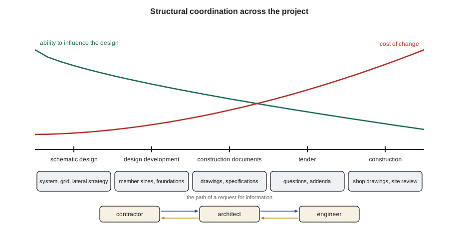
Structural design proceeds in stages that match the architectural ones. In concept or schematic design, the engineer helps choose the system, the grid and the lateral strategy, and gives approximate member sizes and floor depths. This is where the architect gains most from involving the engineer early: decisions about the grid, the location of cores, transfers, cantilevers and long spans have the greatest effect on cost and the least cost to change. In design development, the engineer runs the structural analysis, sizes members, develops foundations and coordinates with the services. In construction documents, the engineer produces the structural drawings and specifications. During construction, the engineer reviews shop drawings, answers questions, inspects critical work and reviews changes.
The cost of change rises steeply through these stages. Moving a column in schematic design costs an hour of drawing; moving it after the foundations are poured can cost as much as the column itself many times over. Szymańska draws the familiar curve: the ability to influence the project falls as the cost of changes rises. She asks the students to remember one practical rule. 'Before you show a plan to a client, show it to your engineer. They will ask three questions: where are the columns, where is the lateral system, and where are the holes. Have answers.'
Space for structure and services
The most frequent coordination problem is space: the structure and the services compete for the same zone between the ceiling and the floor above. Ducts are large, sprinkler mains and drain pipes must slope or cross, and beams are deep. The floor-to-floor height must accommodate the clear height wanted in the rooms, the structure, the services that run below or through it, the ceiling and the floor build-up. Each structural system leaves a different amount of room for services. A flat plate has no beams, so services can run anywhere below it, but it has no space between beams to hide them either. A steel frame has deep beams, but ducts can run between them or through openings in their webs. A mass timber frame often has deep glulam beams that services must run beside or below, because large holes through glulam are restricted.
# Floor-to-floor budget and duct openings in beams (mm)
systems = {                                # structure depth, services zone, ceiling and floor build-up (mm)
    "flat plate": (240, 0, 0, 25),
    "steel beams and deck": (530, 350, 20, 25),
    "glulam beams and CLT": (600, 300, 20, 75),
}
clear = 2600                            # clear height wanted in the rooms
ftf = {}
for name, (struct, services, ceiling, floor) in systems.items():
    ftf[name] = clear + struct + services + ceiling + floor
    print(f"{name:<22} floor to floor {ftf[name]:.0f} mm  (structure {struct}, services {services})")
extra = 4 * (ftf["steel beams and deck"] - ftf["flat plate"])
print(f"Over four floors the steel scheme is {extra:.0f} mm taller than the flat plate")
# rule of thumb for a round opening in a solid beam: middle third of the span, away from supports
depth, span = 600, 7200
for dia, x in [(150, 3600), (250, 3600), (150, 900)]:
    ok = dia <= depth / 3 and span / 3 <= x <= 2 * span / 3
print(f"opening {dia} mm at {x} mm in a beam {depth} mm deep: {'acceptable by the rule of thumb' if ok else 'ask the engineer'}")flat plate floor to floor 2865 mm (structure 240, services 0) steel beams and deck floor to floor 3525 mm (structure 530, services 350) glulam beams and CLT floor to floor 3595 mm (structure 600, services 300) Over four floors the steel scheme is 2640 mm taller than the flat plate opening 150 mm at 3600 mm in a beam 600 mm deep: acceptable by the rule of thumb opening 250 mm at 3600 mm in a beam 600 mm deep: ask the engineer opening 150 mm at 900 mm in a beam 600 mm deep: ask the engineer
The script compares floor-to-floor heights for an apartment floor with 2.6 m of clear height. The flat plate needs about 2.9 m floor to floor, because its services run in the corridor ceilings and in the suites below the slab without a separate zone; the steel and timber schemes need about 3.5 to 3.6 m because of their beam depths and services zones. Over four floors the steel scheme is about 2.6 m taller. For a building limited to a fixed height by zoning, that difference may cost a whole floor of homes; for a building limited by the number of floors, it adds facade area, cost and energy loss. This is why so many apartment buildings in North America are flat plates or light wood frame, and why mass timber housing often uses flat panel floors without beams.
Holes in structure
Services have to pass through structure somewhere, and every hole needs to be planned. Openings in concrete slabs and walls should be shown on the structural drawings and kept away from columns and from the ends of walls; in post-tensioned slabs they must avoid tendons. Openings through concrete beams are possible, with reinforcement around them, but are best placed in the middle third of the span, where shear is low, and near mid-depth, where bending stresses are low. Steel beams can be made with large web openings, either cut and reinforced or as castellated or cellular beams with regular openings formed by cutting and rewelding the web. Wood I-joists and open-web trusses have knockouts and spaces for services; solid glulam and sawn lumber accept only small holes in specific zones.
A useful rule of thumb for a round opening in a solid beam is that it should be no larger than about a third of the beam's depth, centred near mid-depth, and in the middle third of the span. The script's last lines test three openings in a 600 mm beam spanning 7.2 m. A 150 mm opening at midspan passes; a 250 mm opening is too large for the rule; and a small opening near the support, where the shear is highest, needs the engineer's review. The rule is no substitute for the engineer, but it lets the architect sketch services routes that are likely to work.
Drawings, specifications and communication
Structural drawings include general notes, which state the codes, loads, materials and design criteria; foundation plans; framing plans for each floor and the roof; sections and details; and schedules of columns, beams, footings and reinforcement. The architect's drawings must agree with them: the gridlines, column sizes, slab edges, openings, steps in floor levels and depths of beams must match exactly. Conflicts between the architectural and structural drawings are a common source of requests for information during construction. Coordinated building information models, which Digital Design and BIM introduced, help catch these conflicts, but only if the models are kept up to date and checked regularly; clash detection finds the duct through the beam, but someone still has to decide who moves.
Specifications describe the materials, quality and workmanship that the drawings cannot show: concrete strengths and exposure classes, steel grades, welding procedures, wood grades and moisture limits, inspection and testing. In Canada, the National Master Specification and the MasterFormat divisions are widely used, with Division 03 for concrete, 05 for metals and 06 for wood. Communication during construction follows set paths: a request for information from the contractor goes to the architect, who passes structural questions to the engineer; shop drawings and submittals are reviewed and returned with comments; and changes are documented by the architect in change orders or site instructions. Skipping these paths, by an engineer giving instructions directly to a trade, for instance, creates confusion about responsibility and cost.
Working well together
Anand and Fortin end the class by listing what makes architects and engineers good partners. The engineer wants the architect to share the design intent early, not just the plans: why the cantilever matters, what the client values, where flexibility is needed. The architect wants the engineer to offer options, not just answers, and to explain the trade-offs in cost, depth and appearance. Both want decisions recorded, so that a column moved in a meeting is moved on everyone's drawings. Both want the services engineers in the room when the structure is being decided. And both want to visit the site together, because the building is where coordination succeeds or fails.
Szymańska adds one more. 'Learn to sketch structure well enough that your engineer can see what you mean. If you can draw a load path, a lateral system and a section with the beams at the right depth, the engineer will take your ideas seriously, and your ideas will survive.' The students' studio projects will be reviewed in Lesson 12 by an engineer, and she wants them to arrive ready for those three questions.
Worked problem
Fitting a duct in the hub's wing
In the hub's wing, a supply duct 400 mm wide by 250 mm deep must cross the glulam floor beams, which are 570 mm deep at 3.5 m centres, spanning 7.2 m between columns. The ceiling height in the library below is fixed. What are the options?
Show solution
- A hole 250 mm deep through a 570 mm glulam beam is close to half its depth, far beyond the small holes timber codes allow.
- Running the duct below the beams adds about 300 mm to the floor zone, which the fixed ceiling height does not allow.
- Running the duct parallel to the beams, between them, avoids crossing them entirely; the duct then crosses only the CLT panels at the ends of each run.
- Where a crossing cannot be avoided, the duct can pass under the beam at a dropped ceiling over a corridor or storage room.
- The best solution is to plan the main duct routes along the beams from the start, with drops only where ceilings allow.
Answer: Run ducts parallel to the glulam beams, between them, and cross only at a lowered ceiling; do not cut large holes in the beams.
Exercise 11: coordination
- Draw a section through one floor of your studio project at 1:20 showing the structure, the main ducts and pipes, the ceiling and the floor build-up.
- Calculate the floor-to-floor height and compare it with an alternative structural system.
- Mark every place where a duct or pipe crosses a beam or wall, and resolve each crossing.
- Write three questions you would ask your structural engineer in schematic design.
Self-check
- Do I know who is responsible for each part of the structural design?
- Have I left enough room for services in my floor-to-floor height?
- Are all openings in my structure planned and drawn?
Common mistakes
MistakeBringing in the engineer only after the plans are fixed.
InsteadInvolve the engineer in schematic design, when grid, cores and spans can still change.
MistakeIgnoring the services zone when setting floor-to-floor heights.
InsteadAdd structure, services, ceiling and floor build-up to the clear height.
MistakeDrawing ducts through beams without telling anyone.
InsteadPlan openings with the engineer and show them on the structural drawings.
MistakeLetting architectural and structural grids or slab edges disagree.
InsteadCoordinate the drawings or the models regularly and resolve conflicts promptly.
MistakeGiving instructions to trades directly in the field.
InsteadFollow the contract paths: requests for information, submittals and documented changes.
Summary and key terms
- The architect coordinates the design; the structural engineer of record designs and seals the structure; some elements are delegated to fabricators' engineers.
- Early involvement of the engineer pays most, because the cost of changes rises steeply as the project proceeds.
- Floor-to-floor height must hold the clear height, structure, services, ceiling and floor; different systems leave different room for services.
- Openings in structure must be planned: in the middle third of spans, away from columns and supports, within size limits.
- Drawings, specifications, models, requests for information and submittals are the tools of coordination; good partners share intent, options and decisions.
- Engineer of record
- The engineer responsible for the structural design shown on the sealed drawings.
- Delegated design
- Design of a component by the fabricator's engineer to criteria set by the engineer of record.
- Request for information
- A formal question from the contractor about the documents during construction.
- Shop drawing
- A drawing prepared by a fabricator showing how an element will be made and installed.
- Floor-to-floor height
- The vertical distance from one floor surface to the next.
- Castellated beam
- A steel beam with a regular pattern of web openings formed by cutting and rewelding.
Practice problems
Work each problem on paper first, then reveal the answer to check.
Clear height 2.7 m, structure 0.45 m, services 0.3 m, ceiling and floor 0.1 m. What is the floor-to-floor height?
Show answer
3.55 m.
Where in a beam's span should a duct opening ideally be placed?
Show answer
In the middle third of the span, near mid-depth, where shear and bending stresses are low.
What is delegated design?
Show answer
Design of an element such as a steel connection or truss by the fabricator's engineer, to criteria set by the engineer of record.
Why do many apartment buildings use flat plates?
Show answer
They give the thinnest floor zone and the lowest floor-to-floor height, so more floors fit within height limits.
Who should a contractor ask about a conflict between the structural and architectural drawings?
Show answer
The architect, through a request for information; the architect involves the engineer.
Lesson quiz · 5 questions
Score 60% or more to complete this lesson.
Create a free account to save your progress, take quizzes and earn a certificate.