
AERO-410 · Lesson 8 of 12 · 27 min
Propulsion integration
Propulsion integration is where the engine stops being a catalogue item and becomes part of the aircraft. The designer must choose the power rating, place the engines, shape the nacelles, inlets and exhausts, select the propellers, keep the propellers clear of the ground and the fuselage, cool everything that gets hot, and protect the aircraft against fire and failures. On the Petrel the series hybrid adds a power chain of generators, power electronics, cables, motors and a battery, each with its own losses, cooling needs and failure cases. Kenji, who came to the programme from an engine company, leads this work with Élise.
The power chain
In a series hybrid every kilowatt reaching a propeller has passed through several machines. The turboshaft drives a generator; the generator's output is converted by power electronics and carried on cables to the motor controllers; the controllers drive the motors; the motors turn the propellers. Each stage has an efficiency, and they multiply. With a generator efficiency of about 0.96, a combined controller and motor efficiency of about 0.94 and cable losses of about 1 percent, the chain from turboshaft shaft to propeller shaft is about 0.89. That 11 percent loss is the price of the freedom the hybrid gives, and it must be recovered by better propeller placement, battery-assisted take-off and smaller turboshafts running at their best efficiency.
The cruise power follows from the drag polar of Lesson 6. Thrust equals drag, which at a lift-to-drag ratio of 13.0 is the weight divided by 13.0, and the power into the propellers is thrust times speed divided by propeller efficiency. The turboshafts must deliver that power divided by the chain efficiency, and they must do so at 3000 m, where a turboshaft produces less power than at sea level because the air is less dense.
# Petrel 19 powertrain: cruise shaft power, generator sizing with lapse, propeller diameter and battery duty.
import math
W, LD, V, eta_p = 8450 * 9.81, 13.0, 400 / 3.6, 0.82
chain = 0.96 * 0.94 * 0.99
P_prop = W / LD * V / eta_p                        # power into both propellers in cruise
P_gen = P_prop / chain                             # turboshaft output needed
lapse = 0.72                                       # turboshaft power at 3000 m relative to sea level (typical)
install = 0.97                                     # inlet, exhaust and accessory losses
P_sl = P_gen / (lapse * install)
print(f"cruise: {P_prop / 1e3:.0f} kW at the propellers, {P_gen / 1e3:.0f} kW of turboshaft output")
print(f"two turboshafts each rated about {P_sl / 2 / 1e3:.0f} kW at sea level (installed, uninstalled {P_sl / 2 / install / 1e3:.0f} kW)")
# propeller: tip speed limits for noise on the ground and helical Mach in cruise
a_sl, a_3k = 340.3, 328.6
P_motor = 700e3
for D in (2.6, 2.8, 3.0, 3.2):
    for rpm in (1500, 1700):
        tip = math.pi * D * rpm / 60
        Mh = math.hypot(tip, V) / a_3k
        print(f"D {D:.1f} m at {rpm} rpm: static tip {tip:5.0f} m/s ({tip / a_sl:.2f} M)  cruise helical {Mh:.2f}")
D = 3.0
clear = 0.30
hub_height = D / 2 + clear
print(f"chosen D {D} m at 1500 rpm; hub at least {hub_height:.2f} m above ground; spinner-fuselage gap {0.25 * D:.2f} m (0.25 D)")
# battery: generator-out continued climb (one turboshaft lost) for 5 minutes at full motor power
P_need = 2 * P_motor / 0.95                         # both motors at rated power, inverter losses
P_one_gen = P_sl / 2 * install * 0.98               # remaining turboshaft near sea level
deficit = P_need - P_one_gen
E = deficit * 300 / 3.6e6                           # kWh over 5 minutes
pack = 400 * 0.200                                  # 400 kg pack at 200 Wh/kg
print(f"climb with one generator out: deficit {deficit / 1e3:.0f} kW for 5 min = {E:.0f} kWh; pack holds {pack:.0f} kWh, usable 80 percent {0.8 * pack:.0f} kWh")
# revised schedule: 2 min at full power, then 3 min at 85 percent motor power
d2 = 0.85 * P_need - P_one_gen
E2 = (deficit * 120 + d2 * 180) / 3.6e6
print(f"revised schedule (2 min full, 3 min at 85 percent): {E2:.0f} kWh -> margin {0.8 * pack - E2:.0f} kWh")cruise: 864 kW at the propellers, 967 kW of turboshaft output two turboshafts each rated about 692 kW at sea level (installed, uninstalled 714 kW) D 2.6 m at 1500 rpm: static tip 204 m/s (0.60 M) cruise helical 0.71 D 2.6 m at 1700 rpm: static tip 231 m/s (0.68 M) cruise helical 0.78 D 2.8 m at 1500 rpm: static tip 220 m/s (0.65 M) cruise helical 0.75 D 2.8 m at 1700 rpm: static tip 249 m/s (0.73 M) cruise helical 0.83 D 3.0 m at 1500 rpm: static tip 236 m/s (0.69 M) cruise helical 0.79 D 3.0 m at 1700 rpm: static tip 267 m/s (0.78 M) cruise helical 0.88 D 3.2 m at 1500 rpm: static tip 251 m/s (0.74 M) cruise helical 0.84 D 3.2 m at 1700 rpm: static tip 285 m/s (0.84 M) cruise helical 0.93 chosen D 3.0 m at 1500 rpm; hub at least 1.80 m above ground; spinner-fuselage gap 0.75 m (0.25 D) climb with one generator out: deficit 815 kW for 5 min = 68 kWh; pack holds 80 kWh, usable 80 percent 64 kWh revised schedule (2 min full, 3 min at 85 percent): 57 kWh -> margin 7 kWh
Sizing the turboshafts
The program gives 864 kW at the propellers in cruise and 967 kW of turboshaft output. A turboshaft at 3000 m on a standard day produces roughly 72 percent of its sea-level power; that lapse rate is a typical value, and the real figure comes from the engine maker's data for the chosen engine. The installation also costs a few percent through inlet pressure losses, exhaust back-pressure and power taken for accessories. Dividing by both factors gives a sea-level rating of about 692 kW installed per engine, or about 714 kW as the engine maker would quote it on a test stand.
In a conventional twin the engines would be sized by the one-engine-inoperative climb, because one engine must carry the whole aircraft. In the series hybrid that case is shared with the battery: when a generator fails, the battery supplies the missing power for the few minutes of climb needed to reach a safe height, and the remaining generator runs at its maximum rating. That lets the Petrel use two turboshafts sized for cruise rather than for a failure, which is the main reason the hybrid saves fuel: each turboshaft runs close to its rated power for most of the flight, where its specific fuel consumption is lowest.
Propeller selection
The propeller converts shaft power into thrust, and its efficiency depends on its diameter, its blade count and its tip speed. A larger diameter accelerates more air by a smaller amount, which is more efficient, especially at low speed in take-off and climb. But a larger diameter needs more ground clearance, a longer landing gear or a higher wing, and its tips move faster. Tip speed matters twice. On the ground, at full power, high tip speeds make noise, and northern communities often have the strip close to the houses. In cruise the blade tips meet the air at the vector sum of their rotational speed and the flight speed, the helical tip speed, and when its Mach number approaches about 0.85 to 0.9 the tips lose efficiency and make much more noise.
The program tabulates four diameters at two shaft speeds. A 3.0 m propeller at 1500 rpm has a static tip speed of 236 m/s, a tip Mach number of 0.69, and a cruise helical Mach number of 0.79, comfortably below the region where compressibility losses start. A 3.2 m propeller at 1700 rpm would reach a helical Mach number of 0.93, too high. Electric motors make shaft speed a design choice rather than a property of the engine: the motor and its controller can be designed to run at 1500 rpm directly, without a reduction gearbox, which saves mass and maintenance. The team chooses a 3.0 m, six-bladed propeller at 1500 rpm. The extra blades let each blade carry less load at the same diameter and tip speed, which reduces noise further.
Clearances and placement
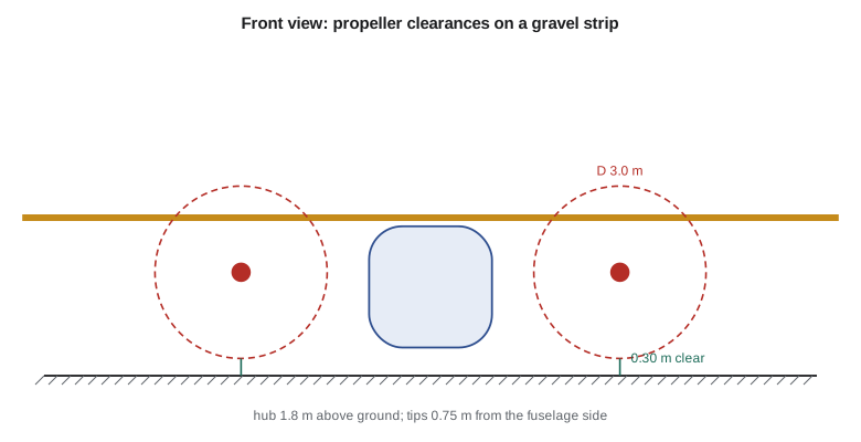
The propeller must clear the ground in every attitude the aircraft can reach on the ground: with the nose gear strut compressed by braking, with a flat main tyre, and with the aircraft rolled slightly by a crosswind. A static clearance of about 0.25 to 0.30 m is a common starting point; on gravel more is better, because stones thrown up by the nose wheel and the propeller's own suction can strike the blades. With a 3.0 m propeller and 0.30 m of clearance the hub must be at least 1.80 m above the ground, which the high wing gives easily, with the nacelle hanging below the wing.
The gap between the blade tips and the fuselage side matters for cabin noise and for structural fatigue: every blade passing a fixed point sends a pressure pulse against the fuselage skin, at a frequency equal to blade count times shaft speed. Gaps of about a quarter to a third of the diameter are usual. The Petrel places the propeller hubs 3.3 m from the centreline, leaving 0.75 m, a quarter of the diameter, between the tips and the fuselage side. The cabin wall in the plane of the propellers gets extra acoustic treatment and thicker skins, and the propeller phase on the two sides is synchronized electronically so that the two pressure fields partly cancel inside the cabin, a technique used on several modern turboprops.
The propellers turn in opposite directions, with the inboard blades moving down. At high angle of attack a propeller's downgoing blade meets the air at a larger angle and produces more thrust than the upgoing blade, so the thrust line shifts toward the downgoing side. With the downgoing blades inboard, the thrust of either live propeller acts closer to the fuselage, which shortens the moment arm of the asymmetric thrust and makes the failure of either motor equally severe, so neither motor is the critical one. On a conventional twin with both propellers turning the same way, the loss of one particular engine is worse than the other. With electric motors, opposite rotation needs no special gearbox and costs nothing.
Nacelles, inlets and cooling
Each Petrel nacelle carries a motor at the front, a turboshaft generator behind it and the generator's inlet, exhaust, oil cooler and fire protection. The turboshaft's air inlet is placed on the upper side of the nacelle, out of the stream of spray and gravel thrown up from the runway, with an inertial separator that turns the airflow sharply so that heavier particles such as ice and sand carry straight on and are dumped overboard. The exhaust exits over the wing's upper surface, away from passengers at the doors and from the ground crew.
Electric machines need cooling of a different kind. A motor and controller chain with a loss of 6 percent at 700 kW produces about 42 kW of heat in each nacelle at full power, at relatively low temperatures compared with a turbine exhaust. Low temperature heat is hard to reject, because the temperature difference to the outside air is small, so the radiators must be large. The Petrel uses a liquid loop with a radiator in the lower nacelle behind a variable inlet; in cruise the inlet is partly closed to cut its drag, and on a hot day climbing out at full power it opens fully. In winter in the Kivalliq region of Nunavut, the reverse problem appears: the battery must be kept warm before take-off, so the thermal system also carries a heater and uses waste heat from the generators to keep the battery within its operating range.
Each nacelle is a fire zone, separated from the wing by a firewall and fitted with fire detection and extinguishing. The battery bay is treated the same way: it is sealed from the cabin, vented overboard, and its cells are arranged so that a failure in one cell cannot spread to its neighbours, a property known as thermal runaway propagation resistance, which battery standards for aircraft now test.
Battery duty
The battery's most demanding job is the generator-out climb. If a turboshaft fails at take-off, both motors still need their full rated power for a few minutes to reach a safe height and accelerate to the climb speed. The remaining generator supplies part of that; the battery supplies the rest. The program's first estimate, both motors at full power for five minutes, gives a deficit of 815 kW and an energy need of 68 kWh. A 400 kg pack at about 200 Wh/kg holds 80 kWh, but only about 80 percent of that is usable to protect the cells, leaving 64 kWh, which is not enough.
Rather than adding battery mass, which would cost about 3.6 kg of take-off mass per kilogram, Élise and Kenji revise the climb schedule: two minutes at full power to clear obstacles, then three minutes at 85 percent motor power, which still meets the company's climb gradient target. The energy needed falls to 57 kWh, leaving a margin of 7 kWh. Hélène points out that the margin must also cover an end-of-life battery in the cold, so the team adds a requirement: the battery must be preheated to its minimum operating temperature before take-off, and the flight management system checks its state of charge and temperature before the take-off power setting is accepted.
Worked problem
Cruise power
Find the power into both propellers for 8450 kg at a lift-to-drag ratio of 13.0, 111 m/s and a propeller efficiency of 0.82.
Show solution
- \(D = W/(L/D) = 82\,900 / 13.0 = 6377\) N.
- \(P = D V / \eta_p = 6377 \times 111.1 / 0.82 = 864\,000\) W.
Answer: About 864 kW.
Worked problem
Helical tip Mach number
A 3.0 m propeller turns at 1500 rpm in a 111 m/s cruise at 3000 m, where the speed of sound is 328.6 m/s. Find the helical tip Mach number.
Show solution
- Tip speed \(= \pi \times 3.0 \times 1500 / 60 = 235.6\) m/s.
- \(\sqrt{235.6^2 + 111.1^2} = 260.5\) m/s; \(260.5 / 328.6 = 0.79\).
Answer: About 0.79.
Worked problem
Generator-out climb energy
The power deficit is 815 kW for 2 minutes, then 85 percent of the need minus the generator for 3 minutes. If the need is 1474 kW and the remaining generator gives 658 kW, find the energy.
Show solution
- Second phase deficit \(= 0.85 \times 1474 - 658 = 595\) kW.
- \(E = (815 \times 120 + 595 \times 180)/3600 = (97\,800 + 107\,100)/3600 = 57\) kWh.
Answer: About 57 kWh.
Common mistakes
MistakeRating the turboshafts at their sea-level power for cruise at altitude.
InsteadApply the altitude lapse and installation losses.
MistakeChoosing the largest propeller for efficiency alone.
InsteadCheck ground clearance, tip speed, noise and helical Mach number.
MistakeForgetting low-temperature heat from electric machines.
InsteadSize radiators for full-power climb on a hot day.
MistakeUsing the battery's full nameplate energy.
InsteadOnly about 80 percent is usable, and less when cold or old.
Summary and key terms
- The Petrel's power chain from turboshaft to propeller has an efficiency of about 0.89.
- Cruise needs 864 kW at the propellers and 967 kW of turboshaft output at 3000 m, so each turboshaft is rated about 690 to 710 kW at sea level.
- A 3.0 m, six-bladed propeller at 1500 rpm keeps the helical tip Mach number at 0.79, with 0.30 m ground clearance and a 0.75 m gap to the fuselage.
- Nacelles house motor, generator, inertial separator, cooling and fire protection.
- A revised climb schedule fits the generator-out climb within the 400 kg battery's usable energy.
- Power chain
- The sequence of machines from fuel-burning engine to propeller in a hybrid system.
- Power lapse
- The fall in engine power with altitude or temperature.
- Helical tip Mach number
- The Mach number of the propeller tip combining rotation and flight speed.
- Inertial separator
- An inlet that turns the airflow sharply so particles and ice are dumped overboard.
- Critical engine
- The engine whose failure most adversely affects handling.
- Thermal runaway
- A self-heating failure of a battery cell that can spread to neighbouring cells.
Practice problems
Work each problem on paper first, then reveal the answer to check.
What is the efficiency of the Petrel's power chain?
Show answer
About 0.89.
Why are the turboshafts sized for cruise rather than for engine failure?
Show answer
The battery covers the generator-out climb.
What propeller was chosen?
Show answer
3.0 m, six blades, 1500 rpm.
How far are the propeller tips from the fuselage?
Show answer
0.75 m, a quarter of the diameter.
How much heat does each motor and controller produce at full power?
Show answer
About 42 kW.
How was the battery shortfall solved?
Show answer
By a revised climb schedule rather than a larger battery.
Lesson quiz · 5 questions
Score 60% or more to complete this lesson.
Create a free account to save your progress, take quizzes and earn a certificate.