
AERO-410 · Lesson 5 of 12 · 26 min
Wing design
The constraint diagram fixed the Petrel's wing area at 36.7 m². Wing design now decides how that area is shaped: its span and aspect ratio, taper, sweep, twist, airfoil sections, thickness, high-lift devices, control surfaces and the volume left for fuel and structure. Each choice trades aerodynamic efficiency against structural mass, cost, handling and practical needs such as fuel volume and landing gear stowage. Tomasz's aerodynamics group leads this work, with Marcus checking every proposal against the wing box results from AERO-310.
Aspect ratio: aerodynamics against structure
Aspect ratio, span squared divided by area, controls induced drag. The induced drag coefficient is \(C_L^2/(\pi A e)\), so a longer, slenderer wing has less induced drag for the same lift, and a higher maximum lift-to-drag ratio. The price is structure: a longer span means a larger root bending moment and a heavier wing box, and a slender wing has thinner, shorter chords, leaving less depth for the spars and less volume for fuel. Oswald's efficiency factor \(e\), which collects the effects of the lift distribution and of drag that grows with lift, falls slightly as aspect ratio rises. Raymer's estimate for straight wings is
# Petrel 19 wing planform: area from wing loading, span, chords, MAC, Oswald factor and L/D.
import math
W0, ws = 8450, 230.0
S = W0 / ws
for AR in (9.0, 10.0, 11.0, 12.0):
    b = math.sqrt(AR * S)
    e = 1.78 * (1 - 0.045 * AR ** 0.68) - 0.64        # Raymer's estimate for straight wings
    CD0 = 0.0300 + 0.0004 * (AR - 10)                 # longer span: a little more wetted area and weight
    K = 1 / (math.pi * AR * e)
    LDmax = 0.5 / math.sqrt(CD0 * K)
    wing_mass = 0.045 * W0 * (AR / 10) ** 0.6          # illustrative wing mass trend with aspect ratio
    print(f"AR {AR:4.1f}: span {b:5.2f} m  e {e:.3f}  L/D max {LDmax:5.2f}  wing mass about {wing_mass:4.0f} kg")
AR, taper = 10.0, 0.45
b = math.sqrt(AR * S)
cr = 2 * S / (b * (1 + taper)); ct = taper * cr
mac = 2 / 3 * cr * (1 + taper + taper ** 2) / (1 + taper)
ymac = b / 6 * (1 + 2 * taper) / (1 + taper)
print(f"chosen: S {S:.1f} m2, span {b:.2f} m, root chord {cr:.2f} m, tip chord {ct:.2f} m")
print(f"MAC {mac:.2f} m at {ymac:.2f} m from the centreline; root thickness at 17 percent {0.17 * cr * 1000:.0f} mm")
V, rho = 400 / 3.6, 1.225 * 0.742
CL = W0 * 9.81 / (0.5 * rho * V ** 2 * S)
print(f"cruise lift coefficient at 3000 m and 400 km/h: {CL:.2f}")AR 9.0: span 18.18 m e 0.783 L/D max 13.68 wing mass about 357 kg AR 10.0: span 19.17 m e 0.757 L/D max 14.07 wing mass about 380 kg AR 11.0: span 20.10 m e 0.731 L/D max 14.41 wing mass about 403 kg AR 12.0: span 21.00 m e 0.706 L/D max 14.70 wing mass about 424 kg chosen: S 36.7 m2, span 19.17 m, root chord 2.64 m, tip chord 1.19 m MAC 2.01 m at 4.19 m from the centreline; root thickness at 17 percent 449 mm cruise lift coefficient at 3000 m and 400 km/h: 0.40
The program shows how slowly lift-to-drag ratio rises with aspect ratio once it is near 10: from 13.7 at an aspect ratio of 9 to 14.7 at 12, while the wing mass rises by about 20 percent across the same range on this illustrative trend. Span also matters on the ground. Northern strips often have snowbanks, lights and small aprons, and hangars at the hub have limited doors. A span of about 19 m fits the hangars the operators already use; 21 m would not. The team chooses an aspect ratio of 10, a span of 19.2 m, and notes in Lesson 12 that a higher aspect ratio would be worth reconsidering if the hangar constraint changes.
Taper, sweep and twist
Taper ratio, tip chord divided by root chord, shapes the spanwise lift distribution. An untapered rectangular wing carries too much lift near the tips compared with the ideal elliptical distribution; a strongly tapered wing carries too much near its tips at high lift and tends to stall there first, which is dangerous because the ailerons lose effectiveness. A taper ratio of about 0.4 to 0.5 gives a near-elliptical loading for an unswept wing, and the Tern's 0.45 is kept. With 36.7 m² and a 19.2 m span this gives a root chord of 2.64 m, a tip chord of 1.19 m and a mean aerodynamic chord of 2.01 m located 4.19 m from the centreline.
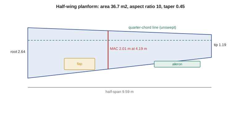
Sweep is used on fast aircraft to delay compressibility effects. At the Petrel's cruise Mach number of about 0.34 it brings no benefit and adds mass, so the quarter-chord line is unswept, which gives a slightly swept-forward trailing edge. Twist, or washout, reduces the angle of attack toward the tip so that the root stalls first, keeping the ailerons effective. The Tern's 2.5 degrees of linear washout, shown in AERO-300 to move the first stall to about 15 percent of the semi-span, is kept with the same airfoil family.
Airfoils and thickness
The airfoil sets the wing's maximum lift, its drag at cruise lift coefficients and its pitching moment. The cruise lift coefficient follows from wing loading, density and speed: at 3000 m and 400 km/h it is about 0.40, comfortably within the low-drag range of a cambered 4-digit or modern general-aviation section. Thickness is a strong lever. A thicker root gives a deeper wing box, lighter spars and more fuel volume, at the cost of a little more drag and a lower critical Mach number, which does not matter at the Petrel's speed. The team chooses about 17 percent thickness at the root, giving about 450 mm of depth for the wing box, tapering to 12 percent at the tip.
Icing is part of the airfoil choice in the Kivalliq region of Nunavut. Sections with sharp leading edges or very aft-loaded pressure distributions can lose much more maximum lift with ice. The AERO-300 analysis showed the Tern's clean maximum lift coefficient falling by about 30 percent with ice; the Petrel uses the same family and the same heated leading edges, and its landing performance is checked with ice shapes on the unprotected surfaces as the certification rules require.
High-lift devices and control surfaces
The landing constraint in Lesson 3 assumed a maximum lift coefficient of 2.6, which the double-slotted Fowler flaps proven on the Tern can deliver. The flaps cover about 60 percent of the span, from the fuselage side to just outboard of the nacelles, with the propeller slipstream over the inboard flaps adding lift at low speed when the motors are at high power. Leading-edge slats were considered and rejected for the same reasons as on the Tern: gravel damage, ice protection complexity and mass.
Ailerons occupy the outboard 35 percent of the span. Their size is set by roll performance requirements, such as banking from 30 degrees one way to 30 degrees the other in a set time at low speed, and by the need to counter engine-out rolling moments. Hélène's controls group checks the aileron size with the roll-mode analysis from AERO-330 and adds spoilers for roll and lift dumping on landing, which shortens the ground roll on gravel by putting weight on the wheels quickly.
Fuel volume and structural integration
The fuel must fit. Integral tanks in the wing box between the front and rear spars, from about 10 percent to 70 percent of the semi-span, hold the fuel. With a box depth of 450 mm at the root falling to about 140 mm at the tank end, a spar spacing of about 45 percent of the chord and allowances for ribs, stringers and expansion space, the tanks can hold about 1750 litres or 1400 kg of fuel. The design mission needs about 1050 kg, so the extra volume becomes the full-tank range in Lesson 11.
Marcus checks the wing box against the high wing's special problem: the carry-through structure must cross over the cabin without stealing headroom. The Petrel uses a box carried through above the cabin ceiling, with the fuselage frames at the front and rear spars forming strong rings. The nacelles add concentrated masses that relieve wing bending in flight but load the wing heavily on landing; the landing gear's position in the fuselage keeps those landing loads out of the wing.
Incidence, dihedral and wingtips
The wing incidence, the angle between the root chord and the fuselage datum, is chosen so that the cabin floor is close to level in cruise. A floor tilted nose-up by a few degrees makes the cart and the passengers walk uphill and raises fuselage drag, because the fuselage meets the air at an angle. At the cruise lift coefficient of 0.40 the wing needs an angle of attack of about 2 degrees at the root once washout is counted, so the root incidence is set at about 2 degrees. The check is repeated at the hold, where the lift coefficient is higher and the floor tilts nose-up by a degree or two more, which is acceptable.
Dihedral, the upward tilt of the wing seen from the front, gives the rolling moment with sideslip that makes an aircraft tend to level its wings. A high wing already produces a strong effect of this kind because of the way the air flows around the fuselage in sideslip, so high-wing aircraft use little dihedral and some use slight anhedral. Too much of the effect is not helpful: it worsens the Dutch roll damping studied in AERO-330 and makes the aircraft roll sharply in gusty crosswinds. The Petrel uses 1.5 degrees of dihedral, a value Hélène's group will confirm with the lateral-directional model once the tail is sized.
Wingtip devices recover some of the energy lost in the tip vortex. A winglet behaves roughly like extra span for induced drag while adding less bending moment at the root than the same span would. For the Petrel the benefit is small, because the aircraft spends most of its time on short legs with long climbs and descents where induced drag matters less than in a long cruise, and a winglet adds mass and certification work on flutter. Tomasz's group keeps a simple rounded tip and records the winglet as an option if the hangar limit later forces a shorter span on a stretched version.
Checking the spanwise loading
The planform choices are checked with a lifting-line or vortex-lattice model of the kind used in AERO-300. The model gives the local lift coefficient along the span at the cruise point and at the stall approach. The cruise loading should be close to elliptical, which keeps induced drag near its minimum for the span; the Petrel's planform reaches a span efficiency within a few percent of the ideal. At high lift the critical result is where the local lift coefficient first reaches the section maximum. With 2.5 degrees of washout and the flaps extended over the inboard span, the first section to reach its limit sits inboard of the nacelles, so the stall begins in a region where it shakes the tail and warns the crew, while the outboard wing and ailerons keep working.
The nacelles and their propellers disturb this neat picture. A rotating slipstream raises the local angle of attack on one side of each nacelle and lowers it on the other, and the extra dynamic pressure behind the propeller adds lift at high power. Both effects are largest at low speed and high power, which is exactly the take-off and go-around case. The team will measure them in a wind tunnel at the National Research Council with powered models, but for the conceptual design they follow the usual practice of choosing propeller rotation directions so that the downgoing blades are inboard, which shortens the moment arm of the asymmetric thrust with one motor stopped, as Lesson 8 explains.
Flutter and stiffness
A long, slender wing with heavy nacelles mounted ahead of it has to be checked for flutter, the self-excited oscillation in which bending and twisting of the wing feed energy into each other from the airstream. Flutter speed rises with torsional stiffness and with mass placed near or ahead of the wing's elastic axis. The nacelles help here because their mass sits ahead of the front spar, but their own mounts and the propeller gyroscopic loads introduce new modes, the whirl modes that caused serious accidents on early turboprops. Marcus's structures group runs a first flutter estimate with the beam model from AERO-310 extended to include the nacelles, and the result sets a minimum torsional stiffness for the wing box that the composite layup must meet. On the Petrel this requirement, rather than strength, sets the skin thickness over the outboard third of the span.
The lesson for conceptual design is that the wing is never chosen on aerodynamics alone. Every planform number in this lesson was checked against structure, fuel volume, handling, flutter, hangar space and gravel operations before it was written into the configuration drawing.
Worked problem
Span and chords
Wing area 36.7 m², aspect ratio 10, taper 0.45. Find span, root chord and tip chord.
Show solution
- \(b = \sqrt{10 \times 36.7} = 19.16\) m.
- \(c_r = 2S/(b(1+\lambda)) = 73.4/(19.16 \times 1.45) = 2.64\) m; \(c_t = 0.45 \times 2.64 = 1.19\) m.
Answer: About 19.2 m, 2.64 m and 1.19 m.
Worked problem
Oswald factor
Estimate \(e\) for an aspect ratio of 10.
Show solution
- \(10^{0.68} = 4.79\); \(1 - 0.045 \times 4.79 = 0.784\).
- \(e = 1.78 \times 0.784 - 0.64 = 0.756\).
Answer: About 0.76.
Worked problem
Cruise lift coefficient
At 3000 m (density 0.909 kg/m³) and 111 m/s, find \(C_L\) for 8450 kg and 36.7 m².
Show solution
- \(q = 0.5 \times 0.909 \times 111.1^2 = 5610\) Pa.
- \(C_L = 8450 \times 9.81 / (5610 \times 36.7) = 0.40\).
Answer: About 0.40.
Common mistakes
MistakeMaximizing aspect ratio without counting the wing mass.
InsteadLift-to-drag gains flatten while wing mass keeps rising.
MistakeAdding sweep to a slow aircraft.
InsteadAt Mach 0.34 sweep adds mass and no benefit.
MistakeChoosing an airfoil without checking iced performance.
InsteadNorthern aircraft must meet requirements with ice shapes.
MistakeForgetting the hangar door.
InsteadSpan is limited by the operators' facilities as well as by aerodynamics.
Summary and key terms
- Wing design shapes the area chosen in sizing.
- Aspect ratio trades induced drag against wing mass and practical span limits; the Petrel uses 10 with a 19.2 m span.
- Taper 0.45, no sweep and 2.5 degrees of washout give a near-elliptical loading with root-first stall.
- A 17 percent root section gives depth for structure and fuel.
- Double-slotted flaps deliver the landing lift, outboard ailerons and spoilers give roll control, and integral tanks hold about 1400 kg of fuel.
- Aspect ratio
- Span squared divided by wing area.
- Taper ratio
- Tip chord divided by root chord.
- Washout
- Reduction of incidence toward the wingtip, so the root stalls first.
- Mean aerodynamic chord
- The chord of an equivalent rectangular wing used as a reference length.
- Oswald efficiency factor
- A factor in the induced drag term that collects lift-distribution and lift-dependent drag effects.
- Integral tank
- A fuel tank formed by the sealed wing box structure itself.
Practice problems
Work each problem on paper first, then reveal the answer to check.
What maximum lift-to-drag ratio does the program give at aspect ratio 10?
Show answer
About 14.1 with the early drag estimate.
Why is the span limited to about 19 m?
Show answer
To fit the operators' hangars.
What is the mean aerodynamic chord?
Show answer
About 2.01 m, 4.19 m from the centreline.
Why is the wing unswept?
Show answer
At Mach 0.34 sweep brings no benefit and adds mass.
How much fuel can the wing tanks hold?
Show answer
About 1400 kg.
Why were slats rejected?
Show answer
Gravel damage, ice protection complexity and mass.
Lesson quiz · 5 questions
Score 60% or more to complete this lesson.
Create a free account to save your progress, take quizzes and earn a certificate.