
AERO-410 · Lesson 6 of 12 · 26 min
Fuselage and cabin layout
Lesson 4 fixed the cabin cross-section and the main arrangement: three seats abreast, a nearly circular section about 2.14 m wide, a high wing and an upswept tail cone with a rear cargo door. This lesson works through the fuselage in detail, from the cockpit at the front to the tail cone at the back, and then estimates the drag of the whole aircraft by adding up its parts. The fuselage is the largest single source of wetted area on most transport aircraft, so its shape matters for cruise fuel as much as for passenger comfort.
The fuselage in sections
Designers think of a transport fuselage as a set of sections, each with its own job. The nose holds the weather radar, the avionics bay and the nose gear well. The cockpit holds two pilots, their instruments and the windshield. The cabin, a parallel section of constant cross-section, holds the passengers. The tail cone tapers to the tail, carries the tail loads and here houses the rear cargo door. A constant-section cabin is cheap to build because the frames, stringers and windows repeat, and it makes a stretched version easy: adding frames in the parallel section lengthens the cabin without redesigning the nose or tail.
For the Petrel the sections are laid out as follows. The nose and cockpit take 3.4 m from the tip of the nose to the cockpit rear bulkhead. The cabin takes 8.2 m for seven rows plus the forward airstair door and a small baggage area. The tail cone takes 4.2 m, giving a total length of 15.8 m. These numbers give a fineness ratio, length divided by diameter, of about 7.5, close to the value at which a body's drag for its enclosed volume is near its minimum. Shorter, fatter bodies have more pressure drag at the rear; longer, thinner ones have more skin friction and are heavier in bending.
The cockpit
The cockpit is sized by the pilots and what they must see and reach. Design standards define a design eye point from which the pilot must have specified vision over the nose and to the sides, and the controls must be reachable by pilots of a stated range of body sizes. The Petrel's operators fly visual approaches to unlit strips in winter twilight, so the team adds a requirement of its own: from the design eye point the pilot must see the strip edge 15 degrees below the horizon over the nose on the approach. That sets the slope of the upper nose and the lower edge of the windshield.
Two pilots are planned because the operators fly in poor weather and many contracts call for two crew, even though aircraft of this size can be certified for one pilot. The cockpit layout keeps the option of single-pilot operation open by placing all controls needed for normal flight within reach of the left seat. The cockpit door, the crew emergency exit and the avionics access hatch are all drawn on the layout, along with the crew's coats and survival kit, which in the Kivalliq region of Nunavut is required equipment and takes real space.
Cabin interior
Inside the cabin, the main numbers are seat pitch, aisle width, headroom and the space for exits and baggage. A seat pitch of about 0.76 m, roughly 30 inches, is typical for short-haul commuters; the Petrel uses 0.76 m with slim-line seats, whose thin backs give winter passengers in heavy coats more knee room than the pitch alone suggests. The aisle is 0.40 m wide at seat-cushion height and wider above the armrests because the cabin wall curves. Standing height in the aisle is 1.75 m, achieved by a slight dip in the floor along the aisle, a common trick on small round-section aircraft.
Cabin features follow from the operators' missions. There is no lavatory: most legs are under an hour, and on aircraft of 19 passenger seats or fewer it is common to omit one to save mass and space. There is no galley beyond a small stowage box. Rules in both countries generally require a flight attendant only for aircraft with more than 19 passenger seats, so 19 is the largest cabin the operators can staff with pilots alone; this is one more reason the Petrel stops at 19. Overhead bins are replaced by a large baggage area aft of the last row and the rear cargo bay, because the curved cabin wall leaves little room above the seats for bags of useful size.
Emergency exits are set by the certification standards, which require a minimum number and size of exits for the seating capacity, with the exits distributed along the cabin and at least one on each side. The Petrel has the forward airstair door on the left, an emergency exit hatch on the right at the wing, and the rear cargo door, which can be opened from inside. The layout must also show that passengers can reach an exit within a short distance from every seat and that the exits are not blocked by the wing or the propellers when they are used on the ground.
Pressurization and structure
The Petrel cruises at about 3000 m, low enough to fly unpressurized with supplemental oxygen available for the occasional higher cruise over weather. Lesson 4 left the option of a low-differential pressurization system for comfort, and the fuselage is designed to take it: a round section, a domed rear pressure bulkhead ahead of the rear cargo door and a flat forward bulkhead behind the avionics bay. Holding the pressure differential to a small value keeps skin thicknesses near what the flight loads would need anyway, so the mass penalty is mainly the bulkheads, the door seals and the system itself, a few tens of kilograms.
The fuselage structure follows the methods of AERO-310: a semi-monocoque shell of frames, stringers and skin. The wing carry-through box crosses above the cabin ceiling, and the frames at the front and rear spars are heavy ring frames that take the wing loads into the fuselage. The main landing gear attaches to strong frames below the floor near the rear spar. The cut-outs for doors and windows need surrounding reinforcement, and the large rear cargo door is the heaviest of them, with its own frames and a stiff sill. Marcus estimates the fuselage mass with the group-weight equations from the preliminary design methods described in Lesson 2 and compares it with the share in the sizing estimate.
Drag build-up
With the fuselage and the rest of the aircraft now laid out, the team replaces the zero-lift drag coefficient of 0.030 assumed in sizing with a component build-up. For each component, the skin-friction coefficient of a flat plate at the component's Reynolds number is multiplied by a form factor for its thickness or fineness, by an interference factor for its junctions with other parts, and by its wetted area, then divided by the wing reference area:
The skin-friction coefficient uses the turbulent flat-plate relation \(C_f = 0.455/(\log_{10} Re)^{2.58}\), which is a little conservative because some laminar flow is ignored. Form factors come from the standard fits in Raymer's book. Separate items, which do not fit the formula, are added for the upswept tail cone, the gravel kit on the nose gear and a general allowance for antennas, gaps, cooling inlets and surface roughness.
# Petrel 19 parasite drag build-up: skin friction x form factor x wetted area for each component.
import math
rho, V, mu = 1.225 * 0.742, 400 / 3.6, 1.69e-5        # 3000 m, cruise
S_ref = 36.7
def cf(L):                                            # turbulent flat plate (Prandtl-Schlichting), mixed transition ignored
    Re = rho * V * L / mu
    return 0.455 / (math.log10(Re) ** 2.58)
# fuselage: length 15.8 m, equivalent diameter 2.12 m
L_f, d_f = 15.8, 2.12
f = L_f / d_f
S_wet_f = math.pi * d_f * L_f * (1 - 2 / f) ** (2 / 3) * (1 + 1 / f ** 2)   # Raymer's wetted-area estimate for a body
FF_f = 1 + 60 / f ** 3 + f / 400
comps = []
comps.append(("fuselage", cf(L_f), FF_f, S_wet_f, 1.0))
# wing: exposed area about 88 percent of reference; t/c 0.15 average, max thickness at 0.35c
S_exp = 0.88 * S_ref; tc, xc = 0.15, 0.35
FF_w = (1 + 0.6 / xc * tc + 100 * tc ** 4)
comps.append(("wing", cf(2.00), FF_w, 2.04 * S_exp, 1.0))
comps.append(("horizontal tail", cf(1.30), 1 + 0.6 / 0.3 * 0.10 + 100 * 0.10 ** 4, 2.04 * 8.3, 1.05))
comps.append(("vertical tail", cf(1.90), 1 + 0.6 / 0.3 * 0.11 + 100 * 0.11 ** 4, 2.04 * 7.4, 1.05))
comps.append(("two nacelles", cf(2.8), 1 + 0.35 / (2.8 / 0.75), 2 * math.pi * 0.75 * 2.8 * 0.9, 1.3))
comps.append(("gear fairings", cf(2.4), 1.3, 2 * 3.0, 1.2))
total = 0.0
print(f"fuselage fineness {f:.1f}, wetted area {S_wet_f:.1f} m2, form factor {FF_f:.3f}")
for name, c, FF, Sw, Q in comps:
    cd = c * FF * Q * Sw / S_ref
    total += cd
    print(f"{name:16s} Cf {c:.5f}  FF {FF:.3f}  Q {Q:.2f}  wetted {Sw:5.1f} m2  CD0 {cd:.5f}")
upsweep = 0.0012                  # aft-body upsweep for the rear cargo door
gravel = 0.0010                   # nose-gear gravel deflector and stone guards
misc = 0.20 * total               # antennas, gaps, cooling inlets, roughness (allowance)
CD0 = total + upsweep + gravel + misc
print(f"components {total:.5f}; upsweep {upsweep}; gravel kit {gravel}; allowance 20 percent {misc:.5f}")
print(f"total CD0 {CD0:.4f} (Lesson 3 and 5 assumed 0.030)")
K = 1 / (math.pi * 10 * 0.757)
print(f"L/D max {0.5 / math.sqrt(CD0 * K):.1f}; cruise L/D at CL 0.40: {0.40 / (CD0 + K * 0.16):.1f}")fuselage fineness 7.5, wetted area 87.0 m2, form factor 1.164 fuselage Cf 0.00215 FF 1.164 Q 1.00 wetted 87.0 m2 CD0 0.00592 wing Cf 0.00292 FF 1.308 Q 1.00 wetted 65.9 m2 CD0 0.00685 horizontal tail Cf 0.00313 FF 1.210 Q 1.05 wetted 16.9 m2 CD0 0.00183 vertical tail Cf 0.00294 FF 1.235 Q 1.05 wetted 15.1 m2 CD0 0.00157 two nacelles Cf 0.00277 FF 1.094 Q 1.30 wetted 11.9 m2 CD0 0.00127 gear fairings Cf 0.00284 FF 1.300 Q 1.20 wetted 6.0 m2 CD0 0.00072 components 0.01817; upsweep 0.0012; gravel kit 0.001; allowance 20 percent 0.00363 total CD0 0.0240 (Lesson 3 and 5 assumed 0.030) L/D max 15.7; cruise L/D at CL 0.40: 13.0
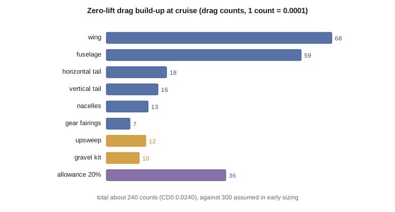
The build-up gives a zero-lift drag coefficient of about 0.0240, or 240 drag counts, compared with the 0.030 used in sizing. The fuselage contributes about a quarter, close to the wing's share, even though it carries no lift. The upswept tail cone costs 12 counts, about 5 percent of the total, which is the price of the rear cargo door. With the refined polar the maximum lift-to-drag ratio rises to about 15.7 and the cruise lift-to-drag ratio at a lift coefficient of 0.40 is about 13.0, better than the 11.5 assumed in Lesson 2.
Élise does not take the full gain at once. The early 0.030 was a cautious value for an aircraft with fixed gear, external fittings and a gravel kit, and build-up estimates are often too hopeful because real aircraft have more gaps, leaks and excrescences than drawings show. She keeps the 20 percent allowance in the estimate and asks Tomasz to confirm the result in a wind tunnel at the National Research Council before the improvement is used to promise range to the operators. For now the better polar is used in Lesson 11 to compute the payload-range diagram, with the note that it is an estimate awaiting test.
Shaping the nose and tail cone
Most fuselage drag is skin friction, which depends on wetted area more than on shape. Shape matters most at the two ends. A blunt nose is acceptable at low speed as long as the flow stays attached around the windshield; a poorly shaped windshield junction can cause a local separation that adds several counts. The rear is more critical. The tail cone must close the body gently enough that the boundary layer does not separate, which usually means a closure angle of no more than about 12 to 15 degrees along the upper and side surfaces. The Petrel's upswept underside breaks this rule deliberately, which is where its upsweep penalty comes from.
Tomasz's group runs a quick panel-method check on the fuselage shape and finds a small region of high suction at the upsweep corner. Rounding the corner with a larger radius and adding a pair of small strakes under the tail cone, a fix used on several freighters with rear doors, reduces the predicted separation. The team records the strakes as a planned feature and keeps the upsweep allowance unchanged until the wind tunnel confirms the benefit.
Worked problem
Fineness ratio
The fuselage is 15.8 m long with an equivalent diameter of 2.12 m. Find the fineness ratio and the form factor \(1 + 60/f^3 + f/400\).
Show solution
- \(f = 15.8 / 2.12 = 7.45\).
- \(FF = 1 + 60/413.5 + 7.45/400 = 1 + 0.145 + 0.019 = 1.164\).
Answer: A fineness ratio of about 7.5 and a form factor of about 1.16.
Worked problem
Skin friction
At 3000 m and 111 m/s the fuselage Reynolds number is \(0.909 \times 111.1 \times 15.8 / 1.69\times 10^{-5} = 9.4\times 10^7\). Find the turbulent \(C_f\).
Show solution
- \(\log_{10}(7.7\times 10^7) = 7.886\); \(7.886^{2.58} = 205\).
- \(C_f = 0.455 / 212 = 0.00215\).
Answer: About 0.00215, matching the program.
Worked problem
Fuselage drag share
The fuselage wetted area is 87.0 m², with \(C_f = 0.00215\), \(FF = 1.164\) and \(Q = 1\). Find its contribution to \(C_{D0}\) on a 36.7 m² wing.
Show solution
- \(0.00215 \times 1.164 \times 87.0 = 0.2177\) m².
- \(0.2177 / 36.7 = 0.00593\).
Answer: About 0.0059, or 59 drag counts.
Common mistakes
MistakeUsing the sizing drag value after the layout exists.
InsteadReplace it with a component build-up as soon as the shape is known.
MistakeLeaving out separate items.
InsteadUpsweep, gear kits and antennas can add tens of counts.
MistakeTaking the build-up result as final.
InsteadKeep an allowance and confirm by test before promising performance.
MistakeDesigning the cabin without the operators' real missions.
InsteadCoats, freight, stretchers and survival kits all take space.
Summary and key terms
- The Petrel fuselage is 15.8 m long with a 3.4 m nose and cockpit, an 8.2 m constant-section cabin and a 4.2 m tail cone, giving a fineness ratio of about 7.5.
- The cabin uses 0.76 m seat pitch, a 0.40 m aisle and 1.75 m standing height, with no lavatory and no flight attendant at 19 seats.
- The structure is ready for low-differential pressurization.
- A component drag build-up gives a zero-lift drag coefficient of about 0.024 and a cruise lift-to-drag ratio of about 13.
- Fineness ratio
- Fuselage length divided by its equivalent diameter.
- Wetted area
- The total surface area in contact with the airflow.
- Form factor
- A multiplier on skin-friction drag that accounts for pressure drag due to thickness or fineness.
- Interference factor
- A multiplier for extra drag where components meet.
- Drag count
- A drag coefficient of 0.0001.
- Design eye point
- The reference position of the pilot's eyes used to check cockpit vision.
Practice problems
Work each problem on paper first, then reveal the answer to check.
What is the Petrel's zero-lift drag coefficient from the build-up?
Show answer
About 0.0240.
How much does the upswept tail cone cost?
Show answer
About 12 drag counts.
Why does the Petrel have no flight attendant?
Show answer
Rules generally require one only above 19 passenger seats.
What seat pitch is used?
Show answer
0.76 m, with slim-line seats.
Why keep the 20 percent allowance?
Show answer
Real aircraft have more gaps and excrescences than drawings show.
What closure angle is usually acceptable on a tail cone?
Show answer
About 12 to 15 degrees.
Lesson quiz · 5 questions
Score 60% or more to complete this lesson.
Create a free account to save your progress, take quizzes and earn a certificate.