
AERO-410 · Lesson 7 of 12 · 25 min
Tail sizing
The tail surfaces have three jobs. They give the aircraft static stability, so that a disturbance in pitch or yaw produces a restoring moment. They let the aircraft trim, balancing the pitching moments of the wing, fuselage and propellers at every speed and centre of gravity position. And they carry the control surfaces, the elevator and rudder, which must be powerful enough for every manoeuvre and failure case, from rotation at take-off to holding straight flight with one motor stopped. Too small a tail fails one of those jobs; too large a tail adds mass and drag on every flight. This lesson sizes the Petrel's tail first by historical coefficients, then checks it against the cases that matter most.
Tail volume coefficients
At the conceptual stage most designers size the tail with tail volume coefficients. The idea is that the tail's power to produce a moment depends on its area times its distance from the wing, so the useful measure is that product made non-dimensional by the wing's size. For the horizontal tail the reference length is the mean aerodynamic chord; for the vertical tail it is the span, because yawing and rolling moments scale with span:
Here \(S_h\) and \(S_v\) are the horizontal and vertical tail areas, \(l_h\) and \(l_v\) are the distances from the wing's aerodynamic centre to the tail surfaces' aerodynamic centres, \(\bar{c}\) is the mean aerodynamic chord, \(b\) the span and \(S\) the wing area. Historical values cluster by aircraft type. Raymer's tables suggest about 0.9 for the horizontal tail and about 0.08 for the vertical tail on twin turboprops. Values outside the usual range are not wrong, but they need a reason: a short-coupled fuselage, an unusual centre of gravity range or an unusual engine arrangement.
The tail arm comes from the layout. On the Petrel the wing's aerodynamic centre sits about 6.9 m from the nose, a quarter of the way along the mean aerodynamic chord, and the horizontal tail's aerodynamic centre about 14.9 m from the nose, giving an arm of 8.0 m. A longer arm means a smaller tail for the same volume coefficient, but a longer, heavier tail cone. The Petrel's arm is set mostly by the cabin and the rear cargo door, so the tail area follows.
# Petrel 19 tail sizing by tail volume coefficients, then a check against the one-motor-out rudder case.
import math
S, mac, b = 36.7, 2.01, 19.17
x_wing_ac = 6.9                 # wing aerodynamic centre from the nose, m
for name, x_tail in (("conventional tail", 14.9), ("T-tail", 15.4)):
    lh = x_tail - x_wing_ac
    lv = lh - 0.4 if name == "conventional tail" else lh - 0.9
    for Vh, Vv in ((0.90, 0.080),):
        Sh = Vh * mac * S / lh
        Sv = Vv * b * S / lv
        print(f"{name:17s} lh {lh:.1f} m  Sh {Sh:.2f} m2  lv {lv:.1f} m  Sv {Sv:.2f} m2")
# one motor out at the minimum control speed: yawing moment from the live motor
P_live, eta, Vmc = 700e3 * 1.10, 0.70, 1.15 * 38.3     # contingency rating, low-speed propeller efficiency
T = P_live * eta / Vmc
y_eng = 3.3                                             # motor thrust line from the centreline
N = T * y_eng
rho, Sv, lv, a_v, tau, dr = 1.225, 7.41, 7.6, 3.2, 0.50, math.radians(25)
q = 0.5 * rho * Vmc ** 2
N_rud = q * Sv * lv * a_v * tau * dr
print(f"live-motor thrust {T / 1e3:.1f} kN, yawing moment {N / 1e3:.0f} kN m")
print(f"rudder moment at 25 degrees {N_rud / 1e3:.0f} kN m -> margin {N_rud / N:.2f}")conventional tail lh 8.0 m Sh 8.30 m2 lv 7.6 m Sv 7.41 m2 T-tail lh 8.5 m Sh 7.81 m2 lv 7.6 m Sv 7.41 m2 live-motor thrust 12.2 kN, yawing moment 40 kN m rudder moment at 25 degrees 47 kN m -> margin 1.16
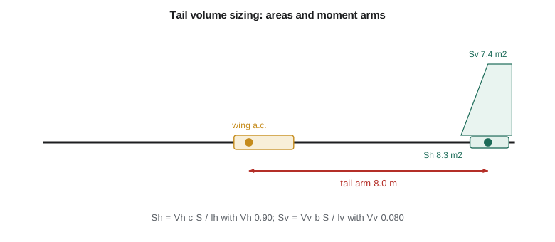
The program gives a horizontal tail of 8.30 m² and a vertical tail of 7.41 m² for the conventional tail. A T-tail, with its horizontal surface on top of the fin and swept back with it, gains about half a metre of arm, so its horizontal tail falls to 7.81 m², a saving of about 0.5 m². That saving does not decide the question. The fin of a T-tail must be stiffer and stronger to carry the horizontal tail at its tip, and the flutter case is harder; the net mass usually favours the conventional tail on aircraft of this size. A T-tail also has a deep-stall risk at very high angles of attack, when the wing's wake can blanket the horizontal tail, and it needs a stick pusher or a careful demonstration of stall behaviour. The team stays with the conventional tail chosen in Lesson 4.
Checking the horizontal tail
Volume coefficients assume that the new aircraft is like the old ones. The Petrel differs in one important way: its centre of gravity range is wider than usual because its large battery and nacelle-mounted generators shift the empty balance, and its passengers sit in a long cabin. Lesson 10 shows that the CG range needed is from about 11 to 36 percent of the mean aerodynamic chord. The horizontal tail must be large enough for the two cases at each end of that range.
At the aft limit the tail sets stability. The stick-fixed neutral point, the CG position at which the aircraft would be neutrally stable, moves aft as the tail grows. With 8.3 m² the neutral point sits at about 50 percent of the mean aerodynamic chord, giving a static margin of about 14 percent at the aft limit, a comfortable value for a transport. At the forward limit the tail sets control. With the CG forward, flaps fully down and the aircraft near the ground at low speed, the elevator must still be able to raise the nose for the landing flare and to rotate on take-off. These two requirements are plotted against tail area on one chart, sometimes called a scissors plot because the two lines cross like the blades of scissors. The smallest tail that meets both is read where the required CG range just fits between the lines. For the Petrel the plot confirms that 8.3 m² meets both ends with a small margin, so the volume coefficient result stands.
Tail icing is a concern for any northern aircraft. A horizontal tail usually carries a download in cruise, which means it works at a negative angle of attack, and with flaps down the downwash from the wing increases that angle further. Ice on the tail's leading edge can reduce its maximum negative lift until the tail stalls, which pitches the aircraft nose-down suddenly, a known cause of accidents on turboprops in icing. The Petrel's horizontal tail has heated leading edges and is given a slightly larger leading-edge radius and a small amount of inverted camber, which moves its stall further from the flaps-down operating point.
Checking the vertical tail with one motor out
For a twin, the vertical tail is usually sized by the engine-failure case rather than by stability. When one motor stops, the other produces a yawing moment equal to its thrust times its distance from the centreline. The rudder must balance that moment at the minimum control speed, the lowest speed at which the pilot can keep straight flight with a bank angle of no more than a few degrees. The company's target is to keep the minimum control speed below about 1.15 times the stall speed in the take-off configuration, so the aircraft can take off at normal speeds without being limited by control.
The program checks this at a minimum control speed of about 44 m/s. The live motor at its contingency rating gives about 12.2 kN of thrust at 3.3 m from the centreline, a yawing moment of about 40 kN m. The rudder, deflected 25 degrees, gives about 47 kN m with the vertical tail of 7.41 m², a margin of 1.16. Hélène asks for more margin before the design freezes, because the propeller slipstream effects and a windmilling or feathered propeller on the dead side change the numbers. Two cheap measures help without enlarging the fin. A dorsal fin extension at the front of the fin delays the fin's stall in sideslip. And the series hybrid gives a measure no conventional twin has: if one generator fails, both motors keep running from the remaining generator and the battery, so the asymmetric case arises only when a motor or its controller fails, not when a power source fails.
Control surfaces and tail details
The elevator usually spans most of the horizontal tail and covers about 25 to 35 percent of its chord; the rudder covers about 30 to 40 percent of the fin chord. Trim tabs on both surfaces let the pilot hold steady flight without force. The Petrel's horizontal tail is mounted on the tail cone, above the upsweep, with a small dihedral to keep it clear of the rear cargo door when the door opens and to raise it slightly above the wing wake.
Tail aspect ratios are lower than the wing's: about 4 to 5 for the horizontal tail and about 1.3 to 1.8 for the fin. A low-aspect-ratio surface stalls at a higher angle of attack, which keeps the tail working when the wing is near the stall. The Petrel's horizontal tail uses an aspect ratio of 4.5 and a span of about 6.1 m, which keeps it inside the fuselage's shadow when the aircraft parks nose-in at small aprons. The fin is 2.6 m tall with an aspect ratio of about 1.5, which leaves the fin tip below the hangar door height the operators gave in Lesson 1.
Finally, the tail's mass at the far end of the fuselage has a strong effect on balance. Every kilogram added at 15 m from the nose moves the empty CG further aft than a kilogram near the wing. That is one reason the tail is built from the same composite materials as the wing, and why the team resists adding equipment in the tail cone.
Feeding the tail back into the design loop
The tail areas now replace the placeholder values used in the drag build-up and in the mass estimate. The 8.3 m² and 7.4 m² from this lesson are the areas Lesson 6 already used, because Arjun ran the tail sizing once before the drag build-up and then confirmed it here; on a real programme the two steps go back and forth several times. Each change in tail area changes the empty mass and its CG, which changes the CG range, which changes the tail area needed. The loop usually settles within two or three passes because the effects are small, but it must be closed. Arjun's spreadsheet links the tail sizing, the mass statement and the CG range so that a change in one updates the others, and the team reviews the closed loop rather than any single result.
Dr. Nakamura's review of the tail asks one further question: what would it take to make the tail smaller? The answer points to the CG range. If the battery could be placed so that the empty CG moved forward by a few percent of the mean aerodynamic chord, or if the cabin loading could be restricted, the range would shrink and so would the tail. The team records this as an opportunity for the detailed design, where every kilogram of tail saved also saves about 3.6 kg of take-off mass through the growth factor from Lesson 2.
Worked problem
Horizontal tail area
With \(V_h = 0.90\), \(\bar{c} = 2.01\) m, \(S = 36.7\) m² and \(l_h = 8.0\) m, find \(S_h\).
Show solution
- \(S_h = V_h \bar{c} S / l_h = 0.90 \times 2.01 \times 36.7 / 8.0\).
- \(S_h = 66.4 / 8.0 = 8.30\) m².
Answer: About 8.3 m².
Worked problem
Vertical tail area
With \(V_v = 0.080\), \(b = 19.17\) m and \(l_v = 7.6\) m, find \(S_v\).
Show solution
- \(S_v = 0.080 \times 19.17 \times 36.7 / 7.6\).
- \(S_v = 56.3 / 7.6 = 7.41\) m².
Answer: About 7.4 m².
Worked problem
Engine-out yawing moment
The live motor delivers 770 kW at a propeller efficiency of 0.70 at 44 m/s, with its thrust line 3.3 m from the centreline. Find the yawing moment.
Show solution
- \(T = P\eta / V = 770\,000 \times 0.70 / 44.0 = 12\,250\) N.
- \(N = 12\,250 \times 3.3 = 40\,400\) N m.
Answer: About 40 kN m.
Common mistakes
MistakeSizing the tail by volume coefficient and stopping there.
InsteadCheck the aft CG for stability and the forward CG for control.
MistakeChoosing a T-tail for its smaller horizontal area alone.
InsteadCount the heavier fin, flutter and deep-stall work.
MistakeIgnoring tail icing.
InsteadIce can stall the tail with flaps down, causing a sudden nose-down pitch.
MistakeSizing the fin by stability alone on a twin.
InsteadThe engine-out case usually governs.
Summary and key terms
- Tail volume coefficients of about 0.90 and 0.080, with an 8.0 m arm, give the Petrel a horizontal tail of 8.3 m² and a vertical tail of 7.4 m².
- A T-tail would save about 0.5 m² of horizontal area but cost mass and add deep-stall risk.
- A scissors plot confirms the horizontal tail meets stability at the aft CG and control at the forward CG.
- The rudder balances the one-motor-out yawing moment with a margin of about 1.16, helped by a dorsal fin and the hybrid's ability to keep both motors running after a generator failure.
- Tail volume coefficient
- Tail area times tail arm, made non-dimensional by wing area and a reference length.
- Tail arm
- The distance from the wing aerodynamic centre to the tail aerodynamic centre.
- Neutral point
- The CG position at which the aircraft is neutrally stable in pitch.
- Static margin
- The distance from the CG to the neutral point as a fraction of the mean aerodynamic chord.
- Minimum control speed
- The lowest speed at which straight flight can be held with one engine inoperative.
- Scissors plot
- A chart of tail area against CG position showing stability and control limits.
Practice problems
Work each problem on paper first, then reveal the answer to check.
What horizontal tail volume coefficient is typical for twin turboprops?
Show answer
About 0.9.
Why is the vertical tail reference length the span?
Show answer
Yawing and rolling moments scale with span.
What static margin does the Petrel have at the aft limit?
Show answer
About 14 percent of the MAC.
What is the rudder margin with one motor out?
Show answer
About 1.16.
Why is tail icing dangerous?
Show answer
It can stall the tail with flaps down and pitch the aircraft nose-down.
What does a dorsal fin do?
Show answer
It delays the fin's stall in sideslip.
Lesson quiz · 5 questions
Score 60% or more to complete this lesson.
Create a free account to save your progress, take quizzes and earn a certificate.