
AERO-410 · Lesson 4 of 12 · 26 min
Configuration layout
Configuration layout is where the numbers of sizing become a shape. The designer decides where the wing goes, how many engines there are and where they sit, what kind of landing gear the aircraft has, how the tail is arranged and how the cabin is laid out around the passengers and cargo. These choices interact: a high wing changes where the landing gear can retract; a rear cargo door changes the fuselage shape and the tail. A good layout satisfies the requirements with the fewest compromises and leaves room for the design to grow.
Starting from the cabin
For a passenger aircraft the cabin is the reason the aircraft exists, so layout usually starts there. The number of seats abreast sets the fuselage width, which drives drag and structure; the number of rows sets the length, which drives tail arm and stability. Nineteen seats can be arranged two abreast with a centre aisle in ten rows, or three abreast with one seat on one side and two on the other in seven rows. Both arrangements are common in the class.
# Petrel 19 cabin cross-section and length: seats abreast, aisle and seat pitch set the fuselage.
import math
seats, abreast, pitch = 19, 3, 0.76          # 1 + 2 seating, 760 mm (30 in) pitch
seat_w, armrest, aisle = 0.46, 0.05, 0.40     # m
rows = math.ceil(seats / abreast)
cabin_w = abreast * seat_w + (abreast + 1) * armrest + aisle
wall = 0.08                                  # frames, insulation and trim, each side
outer_w = cabin_w + 2 * wall
stand = 1.75                                 # standing height in the aisle
outer_h = stand + 0.20 + 2 * wall            # floor beam and structure below, wall above
print(f"rows {rows}: {rows - 1} full rows of {abreast} and a last row with {seats - (rows - 1) * abreast} seat")
print(f"cabin width {cabin_w:.2f} m, fuselage outer width {outer_w:.2f} m, outer height {outer_h:.2f} m")
cabin_len = rows * pitch + 0.9 + 1.2 + 0.8   # seats + entry door and lavatory/galley + baggage + bulkheads
nose, tail = 3.0, 4.6                         # cockpit and nose, tail cone to the empennage
L = nose + cabin_len + tail
d_eq = math.sqrt(outer_w * outer_h)
print(f"cabin length {cabin_len:.2f} m, fuselage length {L:.2f} m, equivalent diameter {d_eq:.2f} m, fineness {L / d_eq:.1f}")
for name, w in (("2 abreast, single aisle", 2 * seat_w + 3 * armrest + aisle), ("3 abreast", cabin_w)):
    r = math.ceil(seats / (2 if name.startswith("2") else 3))
print(f"{name:24s} cabin width {w:.2f} m, rows {r}, cabin length {r * pitch + 2.9:.2f} m")rows 7: 6 full rows of 3 and a last row with 1 seat cabin width 1.98 m, fuselage outer width 2.14 m, outer height 2.11 m cabin length 8.22 m, fuselage length 15.82 m, equivalent diameter 2.12 m, fineness 7.4 2 abreast, single aisle cabin width 1.47 m, rows 10, cabin length 10.50 m 3 abreast cabin width 1.98 m, rows 7, cabin length 8.22 m
The program shows the trade. Two abreast gives a narrow 1.47 m cabin but a 10.5 m cabin length; three abreast gives a 1.98 m cabin and an 8.2 m cabin length. Sam, representing the operators, points out that northern passengers often travel with large carry-on bags and that a standing-height cabin makes boarding and cargo handling much easier in winter clothing. The team chooses three abreast with a 1.75 m standing height in the aisle, giving a fuselage about 2.14 m wide and 2.11 m high outside. Six full rows of three and one single seat by the door make up the 19 seats at a 760 mm pitch.
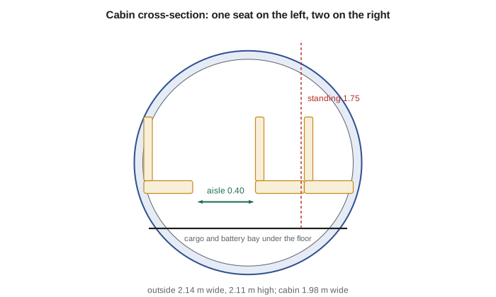
A nearly circular section is chosen even though the cabin is not pressurized for high altitude, because the Petrel will fly at about 3000 m with an optional low-differential pressurization system for comfort and because a round section is efficient structurally and aerodynamically. The floor sits low enough to leave a bay beneath for the battery and some baggage. With a 3 m nose and cockpit, the 8.2 m cabin including the door, a lavatory and a baggage area, and a 4.6 m tail cone, the fuselage is about 15.8 m long with a fineness ratio of about 7.4, within the usual range of 6 to 9 for low-speed transports.
Wing position
Wing position, low, mid or high on the fuselage, is one of the biggest layout decisions. A low wing gives room for retractable gear in the wing, good ditching characteristics and an easy carry-through structure under the floor, but puts propellers close to the ground and makes ground handling around the wing harder. A high wing keeps engines and propellers high above gravel spray and snow, gives passengers a view of the ground, makes loading easy because the fuselage sits low, and naturally gives lateral stability through the high-wing effect. Its drawbacks are a heavier landing gear arrangement, often sponsons or long legs, and a wing carry-through that must pass over the cabin.
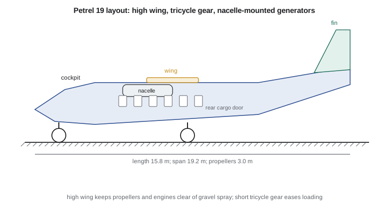
For rough northern strips the high wing wins, as it does for most aircraft in this market. Propellers and generator inlets far above loose gravel suffer much less damage, and the low fuselage sill lets ground crews load freight from the ground without equipment. Tomasz notes that the high wing's extra dihedral effect lets the wing have little or no geometric dihedral.
Engines and propulsion layout
A series hybrid frees the designer from one classic constraint: the propellers no longer have to be mounted directly on the engines that burn fuel. The Petrel could have many small motors along the wing, motors at the wingtips to reduce induced drag, or a pusher arrangement. Each was looked at briefly. Distributed propulsion with many small motors promises better high-lift performance and lower induced drag, but brings many more parts to certify, more complex failure cases and more maintenance in a harsh climate. Wingtip motors reduce induced drag but make engine-out yawing moments much larger.
The team chooses the conservative arrangement: two tractor propellers on wing-mounted nacelles, each driven by an electric motor, with the two turboshaft generators housed in the same nacelles behind the motors. This keeps the power cabling short, keeps the heavy generators near the centre of gravity, places their exhaust well away from the cabin and allows each nacelle to be a self-contained power unit that maintenance crews will recognise. Lesson 10 shows that placing the generators in the rear fuselage, an early idea for cabin quiet, would have moved the centre of gravity far too far aft.
Landing gear and tail
A tricycle gear is standard for transports: it is stable on the ground, gives good visibility and keeps the fuselage level for loading. Fixed gear is tempting for simplicity and rough-field robustness, as on many bush aircraft, but costs drag. The Petrel uses retractable main gear folding into fairings on the lower fuselage and a nose gear with a gravel deflector, and accepts a little more mass for the drag saving on 500 km flights. Lesson 9 places the wheels.
For the tail, the team compares a conventional low tail, a cruciform tail and a T-tail. A T-tail puts the horizontal tail out of the propeller wake and away from gravel thrown up on the ground, and gives a longer effective tail arm, but it is heavier, needs a stiffer fin and brings deep-stall risk at very high angles of attack. A conventional tail on a high-wing aircraft is light and simple but sits in the propeller wake and can be struck by gravel. The team chooses a conventional tail mounted high enough on an upswept tail cone to clear most spray, with the upsweep also making room for a rear cargo door.
Layout drawings and the three-view
The output of this stage is a set of layout drawings, at minimum a three-view showing the aircraft from the side, top and front, with the key dimensions and the positions of major items. Modern teams build the layout in 3D software from the start, but the idea is the same: everything that has size and position, passengers, fuel, battery, motors, gear, systems, is placed so that clashes and centre-of-gravity problems appear early. Arjun keeps a simple spreadsheet of positions alongside the model; the weight and balance analysis in Lesson 10 starts from it.
Layout also checks practical matters that numbers do not show: can mechanics reach the generator for maintenance on a cold ramp; can a stretcher pass through the door for medical evacuation flights, which are important in the north; can the pilots see the strip edge over the nose in a crosswind landing; where do de-icing fluid and snow drain? Sam reviews every layout with these questions, and the cargo door grows twice during the review.
Doors, freight and the combi role
Northern operators rarely fly a passenger-only schedule. On many days the same aircraft carries passengers on the morning leg and groceries, mail, building parts or a snowmobile on the afternoon leg, and a medical evacuation call can arrive at any hour. Sam's operator survey turned this into three layout requirements. First, the cabin must convert between passenger, mixed and all-freight configurations in less than an hour, which means seats on quick-release floor tracks and a cabin floor rated for freight loads, typically several hundred kilograms per square metre. Second, there must be a large door for freight; the Petrel's rear cargo door under the upswept tail cone opens about 1.4 m wide, enough for a standard freight pallet or a stretcher on its trolley. Third, a separate forward airstair door lets passengers board away from the propellers.
The rear door is the reason the tail cone sweeps up. A ramp-style opening needs the fuselage underside to rise behind the cabin, which also gives the tail-strike clearance needed for rotation. The upsweep costs drag because the airflow separates partly over the rising underside, and Lesson 6 adds a specific allowance for it. The team accepts the penalty because the freight role is a large share of the operators' revenue.
Systems placement
A layout is not complete until every major system has a place, with access for maintenance and protection from damage. On the Petrel the battery sits in a ventilated bay under the cabin floor between the wing spars, close to the centre of gravity so that its large mass does not shift the balance, and separated from the cabin by a fire-resistant barrier with its own venting to outside. The power electronics sit just behind the wing, the cooling radiators for motors and electronics share inlets in the nacelles, and the cockpit avionics bay is in the nose ahead of the pressure bulkhead, reached through an external hatch so technicians do not need to enter the cabin.
Ice protection, fuel and hydraulics complete the picture. Fuel stays in the wing, away from the passengers, with the tanks ending outboard of the nacelles so that a propeller blade released in a failure cannot cut into a full tank, a check made with the blade release zone drawn on the layout. Hydraulic or electric actuators for gear and flaps sit in the wing-to-fuselage fairing. The layout drawing shows each item with its mass and centre of gravity, which is the information Lesson 10 needs.
Alternatives kept in the file
Configuration decisions are made early with limited data, and good teams record what they rejected and why. The Petrel file keeps three alternatives with enough detail to reopen them. A low-wing version with the gear in the wing scored better on ditching and wing structure but worse on gravel and loading. A T-tail version, sized in Lesson 7, was lighter in tail area but heavier overall and carried the deep-stall question. A distributed propulsion version with eight small motors promised better low-speed lift but carried much higher certification risk and cost. Each alternative has a short page giving its main dimensions, its estimated mass difference from the baseline, and the condition under which it would become preferred. That last item is the most useful: it tells a future reviewer what would have to change for the decision to change.
Dr. Teresa Nakamura, the chief engineer, reviews the layout before it is frozen for the next design loop. Her review asks whether each item has a reason written down, whether the layout meets the requirements from Lesson 1, and whether anything on it depends on a technology the team has not yet shown to work. The battery, the generators and the power electronics are flagged as the items that need early test evidence, and test articles are budgeted in the programme plan.
Worked problem
Cabin width
Three seats of 0.46 m with four armrests of 0.05 m and a 0.40 m aisle. Find the cabin width.
Show solution
- \(3 \times 0.46 + 4 \times 0.05 + 0.40 = 1.38 + 0.20 + 0.40\).
- \(= 1.98\) m.
Answer: 1.98 m inside, about 2.14 m outside with 0.08 m walls.
Worked problem
Rows and cabin length
19 seats three abreast at a 0.76 m pitch, plus 2.9 m for door, lavatory, baggage and bulkheads. Find the cabin length.
Show solution
- Rows: \(\lceil 19/3 \rceil = 7\).
- Length: \(7 \times 0.76 + 2.9 = 8.22\) m.
Answer: About 8.2 m.
Worked problem
Fineness ratio
A fuselage is 15.8 m long with an equivalent diameter of 2.12 m. Find its fineness ratio.
Show solution
- \(15.8/2.12 = 7.45\).
Answer: About 7.4, within the usual 6 to 9.
Common mistakes
MistakeChoosing the configuration because it looks modern.
InsteadEach feature must earn its place against the requirements and the operating environment.
MistakeLaying out the outside shape before the cabin.
InsteadStart from the payload: seats, aisle, doors and cargo.
MistakeIgnoring maintenance and ground handling.
InsteadCheck access, loading and servicing in the real climate.
MistakePlacing heavy items without checking balance.
InsteadTrack positions from the start; Lesson 10 shows how far CG can move.
Summary and key terms
- Configuration layout turns sizing results into a shape.
- The Petrel's cabin is three abreast with standing height, giving a fuselage about 2.14 m wide and 15.8 m long.
- A high wing keeps propellers and generators above gravel and eases loading.
- Two wing-mounted nacelles each contain an electric motor and a turboshaft generator.
- Retractable tricycle gear, a conventional tail on an upswept tail cone and a rear cargo door complete the layout.
- Configuration
- The arrangement of wing, fuselage, tail, engines and landing gear.
- Seats abreast
- The number of seats across a cabin row.
- Seat pitch
- The distance from a point on one seat to the same point on the seat in front.
- Fineness ratio
- Fuselage length divided by its equivalent diameter.
- Three-view
- A drawing of an aircraft from the side, top and front with key dimensions.
- Distributed propulsion
- Many propulsors spread along the airframe, often electrically driven.
Practice problems
Work each problem on paper first, then reveal the answer to check.
How many rows does three-abreast seating need for 19 seats?
Show answer
Seven: six rows of three and one single seat.
What standing height does the Petrel cabin give?
Show answer
1.75 m in the aisle.
Why does the Petrel use a high wing?
Show answer
To keep propellers and engines above gravel and snow and make loading easy.
Where are the turboshaft generators?
Show answer
In the wing nacelles behind the motors.
What does the upswept tail cone make room for?
Show answer
A rear cargo door.
Why was distributed propulsion not chosen?
Show answer
More parts, complex failure cases and maintenance in a harsh climate.
Lesson quiz · 5 questions
Score 60% or more to complete this lesson.
Create a free account to save your progress, take quizzes and earn a certificate.