
AERO-200 · Lesson 6 of 12 · 22 min
Structures and materials overview
Marcus Webb's structures group occupies the noisiest corner of the Prairiewind Aerospace building, next to the test rig where a full-size section of the Tern's wing is bolted to a steel frame and bent by hydraulic jacks. When Arjun visits, the wing tip has been pulled up nearly 40 cm and strain gauges are recording every few milliseconds. Marcus explains that the structure must be strong enough for the worst load the aircraft will ever see, stiff enough not to flutter, tough enough to tolerate damage, durable enough to last 30 years, and above all light. This lesson introduces where aircraft loads come from, how the structure carries them, and the materials it is made of.
Where the loads come from
In level flight the wing carries a lift equal to the aircraft's weight. In maneuvers and gusts, it carries more. The ratio of lift to weight is the load factor, \(n = L/W\), often called g. In a steady level turn with bank angle \(\phi\), the lift must tilt to provide the turning force while its vertical component still balances the weight, so \(n = 1/\cos\phi\): 1.15 at 30° of bank, 1.41 at 45° and 2 at 60°. Pull-ups, gusts, landing impacts, cabin pressure, engine thrust and inertia loads from heavy items such as batteries and motors all add their own loads.
Certification rules set minimum design loads. Normal-category aircraft must be designed for a positive limit load factor of at least 2.5 to 3.8, depending on weight, and a negative limit of about −1.5. The limit load is the largest load expected in service; the structure must carry it without permanent deformation. The ultimate load is 1.5 times the limit load; the structure must carry it for at least three seconds without failing, although it may be permanently bent. For the Tern, Marcus uses a limit load factor of 3.8, so the ultimate load factor is 5.7.
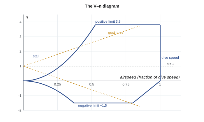
Engineers summarize these requirements on a V–n diagram, which plots load factor against airspeed. At low speeds, the aircraft cannot generate much load factor before the wing stalls, so the boundary follows curved stall lines. At higher speeds, the limit load factors cap the boundary. On the right, the design dive speed limits it. Gust lines, calculated from specified vertical gust velocities, can exceed the maneuver limits for light aircraft with large wings, because a given gust changes the angle of attack and therefore the lift more for such aircraft. The structure must handle every point inside the envelope.
How an aircraft carries load
Early aircraft were built like bridges, with internal trusses of wood or steel tube covered by fabric that carried no load. Modern aircraft use semi-monocoque construction: a thin skin that carries a large share of the load, stiffened by internal members. In the fuselage, the skin is supported by ring-shaped frames that keep its shape and by longitudinal stringers that stop it from buckling. In the wing, the main structure is the wing box: front and rear spars running along the span, ribs running chordwise at intervals, and upper and lower skins stiffened by stringers.
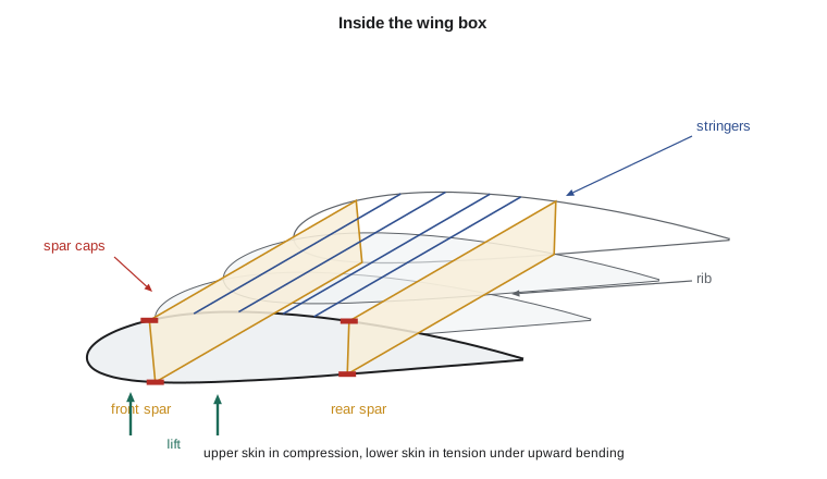
Each part of the wing box has a job. Lift distributed along the span tries to bend the wing upward, putting the upper skin and spar caps in compression and the lower ones in tension. The spar webs carry the vertical shear force. The closed box formed by the spars and skins resists twisting from the lift acting ahead of or behind the box. Ribs maintain the airfoil shape, transfer air loads from the skin to the spars, and divide the skin into panels small enough not to buckle. The wing box also serves as the fuel tank on many aircraft; on the Tern it holds fuel inboard and battery modules in sealed bays.
Bending is the dominant load in the wing. The bending moment is zero at the tip and largest at the root, where the wing joins the fuselage. A simple estimate treats each wing as a cantilever carrying a uniformly distributed lift; the real lift distribution is closer to elliptical and gives a somewhat smaller root moment. The upper and lower spar caps carry the moment as a couple, equal and opposite forces separated by the depth of the box, \(M = Fh\). A deeper box therefore needs smaller caps, which is why the aerodynamicists' choice of a 17 percent thick root airfoil in Lesson 4 matters so much to Marcus.
Worked problem
Root bending moment and spar cap size for the Tern
Estimate the root bending moment of the Tern's wing at ultimate load (n = 5.7, m = 6500 kg or 14,330 lb, b = 17 m or 55.8 ft), treating the lift on each wing as uniformly distributed. If the spar caps are 0.30 m (11.8 in) apart, find the cap force and the cap area needed in aluminum alloy 2024-T3 with an allowable stress of 290 MPa (42 ksi).
Show solution
- Lift on one wing: \(nW/2 = 5.7 \times 63\,765/2 = 182\ \text{kN}\).
- Uniform load on an 8.5 m cantilever: resultant acts at mid-semispan, so \(M = 182 \times 4.25 = 772\ \text{kN·m}\).
- Cap force: \(F = M/h = 772/0.30 = 2575\ \text{kN}\) in each cap, one in tension and one in compression.
- Cap area: \(A = F/\sigma = 2\,575\,000/290 \times 10^{6} = 8.9 \times 10^{-3}\ \text{m}^2 = 89\ \text{cm}^2\).
Answer: In reality the skins and stringers also carry much of the bending, the lift distribution reduces the moment, and the compression side is sized by buckling rather than strength, so detailed analysis gives very different cap sizes. But the estimate shows why wing roots are massive and why a deeper wing box saves weight. It also shows the advantage of carbon-fiber composites: the program finds that a carbon laminate cap would weigh less than a third as much.
# Wing root bending: a cantilever estimate for the Tern
m, g, n = 6500.0, 9.81, 3.8 * 1.5      # mass, gravity, limit load factor times 1.5 safety factor
b = 17.0
semispan = b / 2
lift_half = n * m * g / 2               # lift on one wing at ultimate load
# Treat lift as uniform along the semispan (conservative for bending near the root)
M_root = lift_half * semispan / 2
print(f"Ultimate load factor {n:.2f}; lift per wing {lift_half/1000:.0f} kN")
print(f"Root bending moment {M_root/1000:.0f} kN*m")

# Spar caps carry the moment as a couple: M = F * h
h = 0.30                      # distance between upper and lower spar caps, m
F = M_root / h
for name, sigma_allow, rho in (("aluminum 2024-T3", 290e6, 2780), ("carbon/epoxy laminate", 600e6, 1600)):
    A = F / sigma_allow
    mass_per_m = A * rho
print(f"{name:<22}: cap force {F/1000:.0f} kN, area {A*1e4:.1f} cm^2, mass {mass_per_m:.1f} kg per meter per cap")Ultimate load factor 5.70; lift per wing 182 kN Root bending moment 772 kN*m aluminum 2024-T3 : cap force 2575 kN, area 88.8 cm^2, mass 24.7 kg per meter per cap carbon/epoxy laminate : cap force 2575 kN, area 42.9 cm^2, mass 6.9 kg per meter per cap
Aircraft materials
For most of the past century, aluminum alloys have been the main material of aircraft structures. They are light (density about 2.8 g/cm³), strong after heat treatment, easy to machine and form, and well understood. Alloy 2024 is tough and resists fatigue cracking, so it is used for lower wing skins and fuselage skins that are mainly in tension. Alloy 7075 is stronger and is used for upper wing skins and other compression-loaded parts. Newer aluminum-lithium alloys are lighter and stiffer still.
Titanium alloys are stronger and keep their strength at higher temperatures, and they resist corrosion; they are used in engine mounts, landing gear components, fasteners and areas near hot exhausts, but they are expensive and hard to machine. High-strength steels appear where strength in a small volume matters more than weight, in landing gear and highly loaded fittings. Nickel-based superalloys make the hot sections of jet engines.
Fiber-reinforced composites now make up about half the structural weight of the newest airliners. Carbon fibers, much stronger and stiffer than steel for their weight, are set in an epoxy resin and laid up in layers with fibers oriented to carry the expected loads. Composites resist fatigue and corrosion and allow large, smooth parts with few fasteners. Their drawbacks are cost, sensitivity to impact damage that may not show on the surface, more complex repair, and the need to add metal mesh to carry lightning strike current. The Tern uses a carbon composite wing and tail with an aluminum-alloy fuselage, a common mix for small aircraft.
| Material | Density (g/cm³) | Tensile strength (MPa) | Typical uses |
|---|---|---|---|
| Aluminum alloy 2024-T3 | 2.78 | about 480 | Fuselage skin, lower wing skin |
| Aluminum alloy 7075-T6 | 2.81 | about 570 | Upper wing skin, frames, fittings |
| Titanium alloy Ti-6Al-4V | 4.43 | about 950 | Engine mounts, fasteners, hot areas |
| High-strength steel | 7.8 | 1500 to 1900 | Landing gear, highly loaded fittings |
| Carbon fiber/epoxy (quasi-isotropic laminate) | 1.6 | about 600 | Wings, tails, fuselage panels |
| Glass fiber/epoxy | 1.9 | about 400 | Fairings, radomes, small aircraft |
Engineers compare materials not just by strength but by specific strength (strength divided by density) and specific stiffness (stiffness divided by density). For a tension member of given load, mass is proportional to density divided by strength. For a panel that must not buckle, other combinations of stiffness and density matter more. This is why the right material depends on how the part is loaded, not just on which material is strongest.
Fatigue, damage tolerance and aeroelasticity
An aircraft's structure sees millions of load cycles: gusts, maneuvers, landings and, in pressurized aircraft, one pressurization cycle per flight. Repeated loads well below the static strength can start small cracks at holes and sharp corners, which grow slowly with each cycle. This is fatigue. The de Havilland Comet, the first jet airliner, suffered fatal in-flight breakups in 1954 caused by fatigue cracks growing from corners of fuselage openings. Investigations into those accidents transformed aircraft design.
Modern structures are designed to be damage tolerant: they must carry the required loads even with a crack or damage large enough to be missed at one inspection, and inspection intervals are set so that cracks are found long before they become critical. Fail-safe design provides multiple load paths, so that if one member fails, others carry the load. The 1988 Aloha Airlines accident, in which part of a fuselage roof tore away in flight after widespread small cracks joined up, led to rules on aging aircraft and widespread fatigue damage.
Aircraft structures also bend and twist under load, and this flexibility interacts with aerodynamics, a field called aeroelasticity. A flexible wing that twists nose-up under load gains more lift, which twists it further; above a certain speed this can lead to divergence. More dangerous is flutter, a self-excited vibration in which aerodynamic forces feed energy into a coupled bending and twisting motion, potentially destroying the structure in seconds. Designers prevent flutter with adequate stiffness, mass balancing of control surfaces and careful analysis, and flight tests expand the speed envelope gradually while watching for it.
Testing the structure
Analysis alone is not enough. Aircraft programs test materials as coupons, then elements and details such as joints, then subcomponents like the wing section on Marcus's rig, and finally full-scale airframes. This building-block approach, sometimes drawn as a pyramid, gathers thousands of small tests at the base and a few large ones at the top. The full-scale static test loads the airframe to limit and then ultimate load; the full-scale fatigue test cycles it through two or more lifetimes of simulated flights, often for years, while the first production aircraft are already flying.
Common mistakes
MistakeDesigning to the load in level flight.
InsteadThe structure must carry the limit load factor without permanent deformation and 1.5 times that without failure.
MistakeAssuming the skin of a modern aircraft is just a covering.
InsteadIn semi-monocoque structures the skin carries a large share of bending, shear and torsion.
MistakeChoosing the strongest material for every part.
InsteadThe best material depends on specific strength, stiffness, fatigue, damage tolerance, cost and manufacturability.
MistakeTreating fatigue as an old problem that composites have solved.
InsteadComposites resist fatigue but are vulnerable to hidden impact damage; metals and joints still need fatigue design.
MistakeThinking flutter is just an annoying vibration.
InsteadFlutter is a self-excited instability that can destroy a structure in seconds; it must be ruled out across the flight envelope.
Summary and key terms
- Load factor n = L/W; in a level turn n = 1/cos φ.
- Limit load is the largest expected load, carried without permanent set; ultimate load is 1.5 times limit, carried without failure.
- The V–n diagram bounds the speeds and load factors the structure must withstand.
- Semi-monocoque structures combine load-carrying skins with frames, stringers, spars and ribs; the wing box carries bending, shear and torsion.
- Aluminum alloys, titanium, steels and carbon composites are chosen by specific strength and stiffness, fatigue behavior and cost.
- Damage tolerance, fail-safe design, flutter prevention and building-block testing keep structures safe for decades.
- Load factor
- The ratio of lift to weight, n = L/W, often expressed in g.
- Limit load
- The maximum load expected in service, which the structure must carry without permanent deformation.
- Ultimate load
- Limit load multiplied by the factor of safety of 1.5.
- V–n diagram
- A plot of load factor against airspeed defining the structural design envelope.
- Semi-monocoque
- A structure in which a thin skin, stiffened by frames and stringers, carries much of the load.
- Wing box
- The main load-carrying structure of a wing: spars, ribs and stiffened skins.
- Spar cap
- The flange of a spar, which carries bending loads in tension or compression.
- Fatigue
- Crack initiation and growth under repeated loads below the static strength.
- Damage tolerance
- The ability of a structure to carry required loads with undetected damage until the next inspection.
- Flutter
- A self-excited aeroelastic vibration that can destroy a structure.
Practice problems
Work each problem on paper first, then reveal the answer to check.
Find the load factor in a level turn at 50° of bank.
Show answer
n = 1/cos 50° = 1.56.
An aircraft has a limit load factor of 3.8. What is its ultimate load factor?
Show answer
5.7.
A 1000 kg aircraft pulls 3 g. What lift must the wing produce?
Show answer
L = 3 × 9810 = 29.4 kN.
A wing root moment of 400 kN·m is carried by caps 0.25 m apart. Find the cap force.
Show answer
F = 400/0.25 = 1600 kN.
Which aluminum alloy would you expect on an upper wing skin, and why?
Show answer
7075, because the upper skin is mainly in compression and benefits from its higher strength; 2024's fatigue resistance matters more in tension.
In the program, increase the spar cap separation to 0.36 m. How much lighter are the aluminum caps per meter?
Show answer
Cap force falls by a sixth to about 2146 kN, and the cap mass drops to about 20.6 kg per meter per cap.
Lesson quiz · 5 questions
Score 60% or more to complete this lesson.
Create a free account to save your progress, take quizzes and earn a certificate.