
RCDD-113 · Lesson 7 of 12 · 20 min
Primary and secondary protectors
▶ Video coming soon A video version of this lesson is on the way.
The service provider's engineer, a patient man named Gord Lindahl who had been installing building entrances for thirty years, met Daniel at the Harbourview site in October, when the foundations were in and the entrance conduits had been placed. Gord wanted to know where his protector would go. Daniel had a drawing ready: the protector field on the east wall of the entrance facility, 1.5 metres from where the entrance conduits came through the foundation wall, and 2 metres from the PBB. Gord looked at it, nodded and said, 'You'd be amazed how often I'm told to put it at the far end of the room because that's where the backboard is.'
This lesson covers the devices that stand between outside cables and the equipment inside: the primary protectors required at the building entrance for exposed metallic circuits, the secondary protectors that add protection closer to equipment, and the special cases of coaxial cables and fibre cables with metal in them.
What a primary protector does
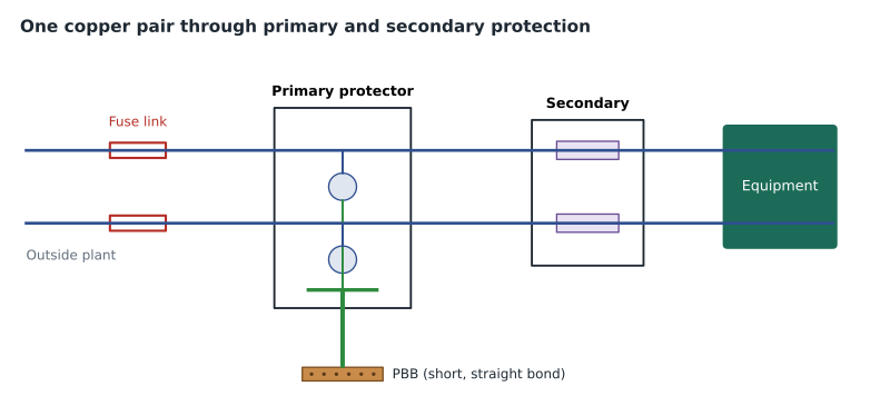
A primary protector connects each conductor of an incoming metallic cable, such as each pair of a copper telephone cable, to the building's bonding network through a device that is normally an open circuit. When the voltage between a conductor and the bonding network rises above the device's breakdown level, the device conducts and diverts current from the conductor to the bonding network. The conductor is then clamped close to the local reference, so the equipment connected to it sees only a small difference.
The primary protector's job is to protect people and the building first, and equipment second. It deals with large energies from lightning and power faults on the outside plant and keeps them out of the building wiring. It is not designed to bring the voltage down to a level that sensitive electronics can survive; that is the job of secondary protection and of the protection built into equipment.
Protector technologies
Three main technologies have been used in primary protectors. Carbon blocks, the oldest, use two carbon electrodes separated by a small air gap; when the voltage is high enough, the gap arcs over. They are cheap but wear with each operation and can become noisy or short permanently, and they are now largely replaced. Gas discharge tubes, the most common today, enclose electrodes in a sealed tube filled with an inert gas; they break down at a predictable voltage, can carry large surge currents and recover afterwards. Solid-state protectors use semiconductor devices, typically thyristor-based, that respond faster and clamp at lower, more precise voltages than gas tubes, at a higher cost and with lower current capacity for very large surges.
Many protector units combine technologies, for example a gas tube for large currents with a solid-state element for speed. Most also include a fail-safe mechanism: if a sustained power fault overheats the unit, a spring-loaded contact or a melting element shorts the conductors permanently to ground. This keeps a power fault from causing a fire inside the building at the cost of putting the line out of service until the unit is replaced, which is the right trade-off.
| Technology | How it works | Strengths | Limitations |
|---|---|---|---|
| Carbon block | Air gap between carbon electrodes arcs over | Low cost | Wears, can become noisy or permanently shorted; largely obsolete |
| Gas discharge tube | Sealed gas breaks down and conducts | Large surge capacity, recovers after operation | Slower response; breakdown voltage varies with rate of rise |
| Solid-state (thyristor) | Semiconductor switches on at a set voltage | Fast, precise, low clamping voltage | Higher cost; lower capacity for the largest surges |
| Hybrid | Gas tube with a solid-state element | Combines capacity and speed | More complex; cost |
Where the primary protector goes
Codes require a listed or certified primary protector on each metallic communications circuit that is exposed, as lesson 6 defined. The protector is to be located as close as practical to the point where the cable enters the building, inside or outside, so that the length of unprotected conductor inside the building is as short as possible. Section 60 of the Canadian Electrical Code sets out the requirements, including the conditions under which a protector without fuses may be used and how the protector is to be bonded.
The protector's grounding terminal must be connected to the building's grounding system with a bonding conductor that is as short and straight as practical. The code sets a minimum conductor size, limits on its length in many cases, and a list of acceptable connection points in order of preference, starting with the building's intersystem bonding connection point at the service or the grounding electrode system. In a building with a telecommunications bonding network, the PBB placed close to the protector and to the service provides that point, provided it is bonded to the service as lesson 3 described and the AHJ accepts it.
Daniel had three goals in placing the protector field: a short run of unprotected cable from the conduit entry, a short straight bond to the PBB, and enough working space in front of the protector panel for the provider's technicians. Gord confirmed the protector would be a building entrance terminal with plug-in gas tube units, fused at the cable by fine-gauge sections in the outside plant, and that the provider's equipment would be bonded to the PBB with the conductor size the provider's standard required.
Fuse links and fused protectors
Under a power contact, a protector that conducts to ground can carry a large current for a long time. If nothing limits that current, the cable conductors between the outside plant and the protector can overheat. Two arrangements deal with this. A fused protector includes a fuse in each conductor ahead of the protective element. A fuseless protector relies on a fuse link in the outside cable: a short section of finer-gauge conductor, upstream of the building, that melts under sustained overcurrent and opens the circuit before the conductors inside the building can overheat. The code allows fuseless protectors only when the conditions it lists are met, which usually include the presence of such a fuse link or a cable that is otherwise protected.
The fuse link is normally part of the service provider's outside plant design, which is a good example of why coordination with the provider matters. Daniel asked Gord to confirm in writing that the incoming cable included fuse links appropriate for the fuseless protectors he planned to install, and noted the confirmation in the design records.
Secondary protection
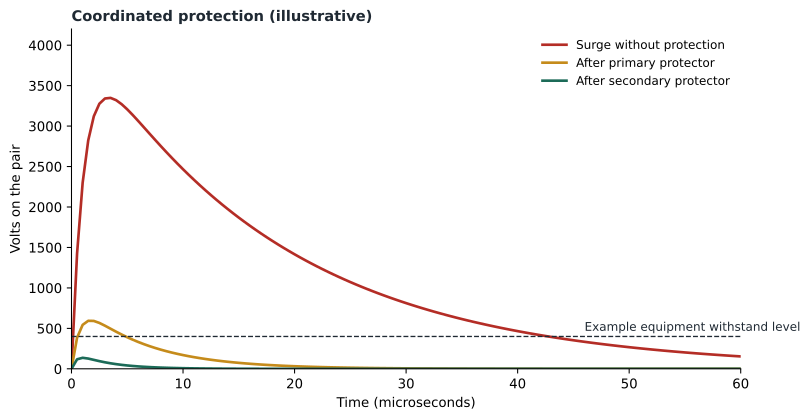
A primary protector leaves a residual voltage on the line: the voltage at which it conducts plus the voltage along its bonding conductor. That residual can still be several hundred volts for a short time, more than many electronic ports can withstand. Secondary protectors, installed closer to the equipment, reduce it further. They typically use solid-state elements with a lower clamping voltage and include current-limiting elements, such as positive temperature coefficient resistors or small fuses, that protect against sneak currents: small sustained currents, below the level that would operate a primary protector, that can still overheat wiring or equipment over time.
Secondary protectors are not a substitute for primary protection. They are designed for the smaller energy left after the primary protector has acted, and they need to be coordinated with it. If a secondary protector clamps too hard and too early, it may try to carry energy that should have been diverted at the primary, and fail. Protector makers publish guidance for coordination, and listing standards for secondary protectors include tests for that purpose.
At Harbourview, the copper pairs from the provider's entrance terminal served the building's emergency elevator phones, fire alarm communicator lines and a small number of legacy analogue lines for the clinic's fax machines and alarm panels. Daniel specified secondary protection at the point where those lines were cross-connected to the building cabling in the main equipment room, with protectors listed for the circuits they served, and bonded the secondary protector panel to the PBB.
Coaxial cables and antennas
Coaxial cables from rooftop antennas and from cable television or broadband providers have a metallic shield that must be bonded where the cable enters the building. For antenna feeds, good practice is to bond the shield at the top of the mast near the antenna, at the bottom of the mast or where the cable leaves the mast, and at the building entry, using grounding kits made for the cable type. A coaxial surge protector at the entry, bonded to the nearest busbar, protects the centre conductor.
At Harbourview, the cellular distributed antenna system donor antennas and the two-way radio antenna on the roof fed coaxial cables down the east shaft to the level 4 telecommunications room. Daniel bonded each cable shield at the mast, bonded the mast to the lightning protection system and roof steel, and placed a coaxial protector on each cable at the rooftop antenna enclosure, bonded to the rooftop SBB. The DAS and radio equipment makers' installation guides set the details, and the electrical engineer confirmed the mast bonding matched the lightning protection design.
Fibre cables with metallic members
Optical fibres do not conduct electricity, but many fibre cables contain metal: steel or aluminium armour for rodent and crush protection, metallic strength members, or copper pairs combined with fibre in hybrid cables. A conductive fibre cable entering a building can carry surge and fault current on its metallic members just as a copper cable can. Codes require those members to be bonded to the building's grounding system as close as practical to the point of entrance, or, in some cases, to be interrupted by an insulating joint near the entrance so that no metal path continues into the building.
The service provider's fibre entrance cable at Harbourview was armoured. Gord's crew would bond the armour at the splice enclosure in the entrance facility with a kit made for the cable, using a conductor to the PBB. The campus link, by contrast, was specified as an all-dielectric cable with no metal at all, so it needed no bonding and no protection, which was one of the reasons Roz had pushed for it.
| Incoming cable | What needs bonding or protection | Where |
|---|---|---|
| Copper service cable | Each pair through a primary protector; cable shield bonded | Entrance facility, close to entry, bonded to the PBB |
| Copper pairs to sensitive equipment | Secondary protection after the primary | At the cross-connect or near equipment |
| Coaxial antenna feed | Shield bonded at the mast and at entry; coaxial protector | Mast, rooftop enclosure, bonded to the nearest busbar |
| Armoured or conductive fibre cable | Metallic members bonded, or interrupted by an insulating joint | As close as practical to the entrance |
| All-dielectric fibre cable | Nothing | Not applicable |
Worked problem
Checking the protector bond
The provider proposes placing the protector panel on the west wall of the entrance facility, about 7 metres from the PBB, because that wall has more free space. The cable enters on the east wall. Explain what Daniel should say and propose an alternative.
Show solution
- A west-wall location puts about 7 metres of unprotected cable inside the building between the entry and the protector, which the code is trying to minimize.
- It also lengthens the bond from the protector to the PBB to roughly 7 metres plus routing, and the inductance of that bond would raise the residual voltage on every protected pair during a surge, as lesson 6 showed.
- The alternative is to keep the protector on the east wall near the conduit entry and to rearrange the backboard layout there, or to add a second PBB-bonded busbar extension near the protector field if the room layout truly requires it.
- Daniel should note the requirement in the specification and on the drawing so that the location is fixed before installation.
Answer: Keep the protector close to the cable entry and close to the PBB; rearrange the wall rather than lengthen the bond.
Common mistakes
MistakeMounting the protector wherever there is free backboard.
InsteadPlace it as close as practical to the cable entry, with a short straight bond to the PBB.
MistakeRelying on secondary protectors alone.
InsteadInstall listed primary protection on exposed circuits and coordinate secondary protection with it.
MistakeForgetting the armour on a fibre cable.
InsteadBond the metallic members of conductive fibre cables near the entrance, or use all-dielectric cable.
MistakeBonding a coaxial shield only inside the building.
InsteadBond antenna feed shields at the mast and at the building entry, and protect the centre conductor.
Summary and key terms
- A primary protector diverts surge and fault energy from incoming conductors to the bonding network, protecting people and the building first.
- Gas tubes, solid-state and hybrid protectors have replaced carbon blocks; fail-safe features short the line under sustained faults.
- Locate primary protectors as close as practical to the cable entry, with a short, straight bond to the PBB.
- Fused protectors or fuse links in the outside plant prevent overheating under power contact.
- Secondary protectors reduce the residual voltage and guard against sneak currents; they must be coordinated with the primary.
- Bond coaxial shields at the mast and entry, and bond or interrupt metallic members of fibre cables at the entrance.
- Primary protector
- A device at the building entrance that diverts surge and fault energy on incoming conductors to ground.
- Secondary protector
- A device closer to equipment that limits residual voltage and sneak currents after primary protection.
- Gas discharge tube
- A sealed tube of inert gas that conducts when the voltage across it exceeds its breakdown level.
- Fuse link
- A short, finer-gauge section of outside plant cable that melts under sustained overcurrent.
- Sneak current
- A small sustained current, below primary protector operation, that can overheat wiring or equipment.
- Conductive optical fibre cable
- A fibre cable that contains metallic members such as armour or strength members.
Practice problems
Work each problem on paper first, then reveal the answer to check.
What is the main job of a primary protector?
Show answer
To divert surge and fault energy on incoming conductors to the bonding network, protecting people and the building first.
Why must the protector be close to the cable entry?
Show answer
To minimize the length of unprotected conductor inside the building.
What is a sneak current?
Show answer
A small sustained current below primary protector operation that can overheat wiring or equipment.
What must be done with the armour of a fibre cable entering a building?
Show answer
Bond it as close as practical to the entrance, or interrupt it with an insulating joint where the code allows.
Lesson quiz · 5 questions
Score 60% or more to complete this lesson.
Create a free account to save your progress, take quizzes and earn a certificate.