
RCDD-113 · Lesson 9 of 12 · 20 min
ICT power distribution and circuits
▶ Video coming soon A video version of this lesson is on the way.
In the middle of the design phase, Priya sent Daniel a short email: 'I need loads for every TR and the data room by Friday, and your receptacle requirements. If you don't give me numbers, I'll use the usual allowance, and you won't like it.' Daniel had been expecting it. The electrical engineer designs the power system, but she can only size it well if the RCDD tells her what the ICT spaces need. Under-sized circuits trip when equipment is added. Over-sized allowances waste money and cooling capacity, and generic allowances miss the specific needs of ICT equipment, such as redundant power feeds and locking connectors.
This lesson covers how an RCDD defines power requirements for ICT spaces: estimating loads, choosing circuits and receptacles, providing redundancy, isolated ground circuits and their proper use, power over Ethernet, and the relationship between power, heat and cooling.
Power in telecommunications spaces
Every telecommunications room, equipment room and data room needs its own power. The TIA standard for telecommunications spaces and pathways, ANSI/TIA-569, and owner standards describe minimum provisions, typically including dedicated branch circuits for equipment, separate convenience receptacles for tools and test equipment, and a power panel in or near the room for larger spaces. The circuits serving ICT equipment should not be shared with other building loads, because a coffee maker or a vacuum cleaner on the same circuit can trip it or inject noise.
Placing a small panel in or next to each telecommunications room has several advantages. Branch circuits are short, which reduces voltage drop and the impedance of the equipment grounding conductors. The panel's equipment ground bus can be bonded to the room's SBB, so the power and telecommunications references in the room are tied together. And the staff who manage the room can see and reset breakers without going to another floor. At Harbourview, Priya planned a panel in each TR and a larger panel for the data room, each fed from the building's distribution, with the data room panel fed through the central UPS described in lesson 10.
Large buildings often distribute power at a higher voltage and step it down near the loads with transformers. In Canada, a common arrangement is distribution at 347/600 V with dry-type transformers to 120/208 V for receptacles and ICT equipment. Each transformer is a separately derived system with its own neutral-to-ground bond, as lesson 2 explained, and its grounding is designed by the electrical engineer. The RCDD should know where those transformers are, because the panels they feed become local references for the ICT spaces they serve, and their bonding to the building steel and to the nearby SBB matters.
Estimating the load
ICT loads are estimated from the equipment the room will hold, with an allowance for growth. For each piece of equipment, the maker's data sheet gives the power consumption, often as a typical value and a maximum. Nameplate ratings on power supplies are usually much higher than actual consumption, because they describe the supply's capacity, not the equipment's draw. Using nameplate ratings for every device overstates the load and leads to oversized and inefficient systems; using typical values without margin understates it.
The largest variable in modern telecommunications rooms is power over Ethernet. A switch that powers access points, phones, cameras and building devices may draw several times more power for its PoE ports than for its own electronics. The switch's PoE budget, the maximum power it can deliver to connected devices, sets the upper limit, but the expected load depends on what is connected. Daniel estimated each TR's PoE load from the device counts on the floor plans and the power class of each type of device.
# Load estimate for TR-3 at Harbourview (watts). PoE device counts come from the floor plans.
switch_base = 4 * 120                      # four 48-port switches, electronics only
poe = {"wireless access points": (14, 25.5),
       "IP phones": (60, 7.0),
       "cameras": (6, 12.95),
       "building sensors and controllers": (22, 4.0)}
poe_load = sum(n * w for n, w in poe.values())
other = 180 + 150                          # building automation cabinet and a small UPS's losses
total = switch_base + poe_load + other
growth = 1.25                              # a growth allowance of one quarter, written as a factor
design = total * growth
print("PoE load:", round(poe_load), "W")
print("total now:", round(total), "W; design load:", round(design), "W")
print("current at 120 V:", round(design / 120, 1), "A")
print("heat to remove:", round(design), "W =", round(design * 3.412), "BTU/h")PoE load: 943 W total now: 1753 W; design load: 2191 W current at 120 V: 18.3 A heat to remove: 2191 W = 7475 BTU/h
The estimate gave Priya what she needed: a design load for each room, the current at the circuit voltage and the heat the cooling system must remove. Every watt of electrical power delivered to ICT equipment in a room ends up as heat in that room or at the PoE devices on the floor. The PoE portion of the load is consumed mostly at the devices themselves, out on the floor, so the heat in the TR is somewhat less than the electrical input; Daniel noted that in the cooling information for the mechanical engineer.
Circuits and receptacles
ICT equipment is supplied through power distribution units in racks or directly from receptacles. For small rooms, 120 V, 20 A circuits with standard receptacles may be enough. For larger rooms and for equipment with high-capacity power supplies, 208 V circuits at 20 or 30 A to rack PDUs are more efficient: the same power at a higher voltage needs less current, which reduces losses and lets more equipment share a circuit. Locking receptacles and plugs prevent accidental disconnection.
Branch circuits are loaded to a fraction of their rating for continuous loads, as the code requires, so a 20 A circuit is typically designed for about 16 A of continuous load. Daniel's request to Priya listed, for each TR, two dedicated 208 V, 30 A circuits to rack PDUs (one for each power feed), two 120 V, 20 A circuits for equipment that needed standard receptacles, one 120 V, 20 A convenience circuit with receptacles on the walls for tools, and a circuit for the building automation cabinet.
| Circuit | Purpose | Typical connector | Notes |
|---|---|---|---|
| 208 V, 30 A, feed A | Rack PDU on the primary power path | Locking receptacle | From the TR panel on generator power, through a rack UPS |
| 208 V, 30 A, feed B | Second rack PDU for dual-corded equipment | Locking receptacle | From a separate source or panel section where available |
| 120 V, 20 A, dedicated | Equipment with standard plugs | Standard duplex or locking receptacle | Not shared with other loads |
| 120 V, 20 A, convenience | Tools, test equipment, laptops | Standard duplex receptacles on walls | Not for equipment in racks |
| 120 V, 20 A, building automation | Controllers and their power supplies | Per the controls designer | May be on emergency power |
Redundant power feeds
Most enterprise switches, servers and storage systems have two power supplies, each with its own cord, so that the failure of one supply or one feed does not take the equipment down. That redundancy is only real if the two cords are on different circuits, ideally from different sources. A rack with two PDUs plugged into the same circuit, or into two circuits on the same breaker panel with no independent source, protects only against a power supply failure.
In the data room, Priya provided two separate UPS-backed distribution paths, called A and B, each with its own panel section, and each rack had one PDU on each path. In the TRs, the building's size did not justify two UPS systems per floor, so both PDUs in each rack were fed through a small rack UPS from the TR's panel, which was itself on the generator. Daniel documented that the TR redundancy protected against power supply and circuit failures but not against the failure of the panel, and the owner accepted it.
Isolated ground circuits
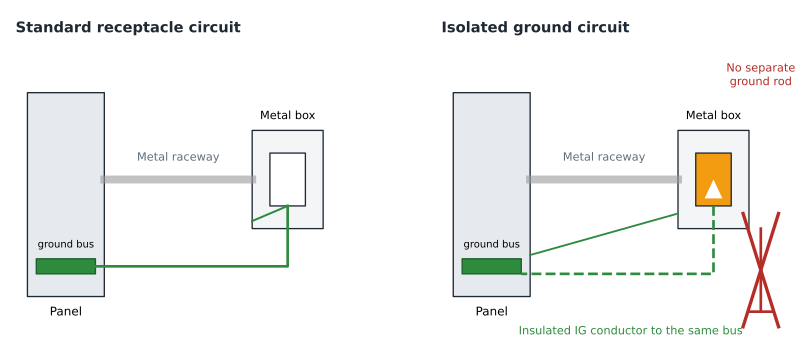
Isolated ground receptacles are often misunderstood. An isolated ground, or IG, receptacle has its grounding terminal insulated from its mounting yoke, so that the receptacle's grounding pin connects only to an insulated equipment grounding conductor run back to the panel or service, rather than to the metal box and raceway. The aim is to keep noise currents on the raceway from reaching the equipment's ground. The receptacle and its separate conductor are permitted by the Canadian Electrical Code under specific conditions, and IG receptacles are identified by an orange triangle or orange colour.
What an isolated ground circuit is not is a separate, independent ground. The isolated conductor still runs back to the same electrical grounding system and connects to it in the panel or at the service. It must never connect to a separate ground rod. And the metal box and raceway must still be grounded through their own path. Done properly, IG circuits are legal and safe; done improperly, they become the dangerous isolated grounds that lesson 1 warned against.
Whether IG circuits help is debatable. They were popular in the 1980s and 1990s for computer rooms, but modern equipment is less sensitive and good bonding of the equipment and racks often matters more. Many designers now avoid them in ICT spaces because equipment in a rack bonded to the SBB effectively connects the IG conductor to the room's bonding network anyway, defeating the isolation. Roz's practice was to use standard grounding circuits and a well-bonded rack unless an equipment maker specifically required IG circuits, and the Harbourview design used none.
Power over Ethernet and cable heating
PoE moves power from the TR to devices on the floor through the data cabling. That is convenient, but it puts current through bundled cables, and current heats conductors. In a large bundle of cables all carrying high-power PoE, the cables in the middle can warm significantly, which increases their insertion loss and, at high temperatures, can exceed the cable's rating. TIA guidance on supporting remote powering over balanced twisted-pair cabling, TSB-184-A, and the electrical codes address bundle sizes and conductor sizes for high-power PoE.
The Canadian Electrical Code sets limits for cables carrying power, which depend on the conductor gauge, the bundle size and the cable's temperature rating. For Harbourview, Daniel limited bundle sizes for cables serving access points and cameras, specified 23 AWG Category 6A cable throughout, which runs cooler under PoE than thinner conductors, and avoided enclosed spaces where many PoE cables would be packed together.
Power quality and shared neutrals
ICT equipment uses switching power supplies, which draw current in short pulses rather than smooth sine waves. On three-phase systems, the harmonic currents these supplies produce add together in the neutral instead of cancelling, so a neutral shared by three circuits can carry more current than any of the phase conductors. Electrical engineers handle this by avoiding shared neutrals on ICT branch circuits, sizing neutrals generously on feeders and choosing transformers rated for non-linear loads. The RCDD does not design these measures but should recognize them, and should ask about them when an existing building's panels serving ICT rooms run hot or trip without obvious cause.
Coordinating with the mechanical engineer
Because every watt of ICT power becomes heat, power and cooling are two sides of the same calculation. Each TR's design load is also its cooling load, adjusted for PoE heat that leaves the room. The mechanical engineer needs to know the heat load, whether it is continuous, whether cooling must continue during a power outage and what temperature and humidity range the equipment needs. Daniel gave the mechanical engineer a one-page summary for each room with the design load in watts , the operating hours (continuous) and a note that TR cooling must be on emergency power.
Worked problem
Checking a circuit request
TR-3 has a design load of about 2,200 W. Daniel plans to feed two rack PDUs from two 208 V, 30 A circuits. Check whether one circuit could carry the full load if the other failed, given that continuous loads are limited to 0.8 of the circuit rating.
Show solution
- Allowed continuous current on a 30 A circuit is 0.8 × 30 = 24 A.
- At 208 V, 24 A corresponds to about 208 × 24 = 4,992 W, roughly 5 kW.
- The design load of about 2,200 W is less than half of that.
- So one circuit can carry the whole room if the other fails, which is what dual feeds need.
Answer: Yes. One 208 V, 30 A circuit can carry about 5 kW continuously, more than twice the TR-3 design load.
Common mistakes
MistakeUsing nameplate power ratings for every device.
InsteadUse measured or typical consumption plus a growth allowance, checked against PoE budgets.
MistakePlugging both PDUs in a rack into the same circuit.
InsteadFeed redundant PDUs from separate circuits, and from separate sources where the design allows.
MistakeConnecting an isolated ground conductor to a separate ground rod.
InsteadRun the IG conductor back to the same panel or service grounding system.
MistakeIgnoring PoE heat in large cable bundles.
InsteadLimit bundle sizes and follow the code and TIA guidance for powered cabling.
Summary and key terms
- ICT spaces need dedicated circuits; a panel in or near each TR shortens circuits and allows bonding to the SBB.
- Estimate loads from typical consumption plus growth, with PoE often the largest part.
- 208 V circuits to rack PDUs are efficient; continuous loads are limited to a fraction of circuit rating.
- Redundant power supplies need separate circuits, and ideally separate sources.
- Isolated ground circuits use an insulated conductor back to the same grounding system, never a separate rod.
- Every watt of ICT power becomes heat; give the mechanical engineer the load and continuity needs.
- Power distribution unit (PDU)
- A rack-mounted strip or unit that distributes power to equipment.
- PoE budget
- The maximum power a switch can deliver to connected devices over its ports.
- Isolated ground (IG) receptacle
- A receptacle whose grounding terminal is insulated from its yoke and connected only to an insulated grounding conductor.
- Continuous load
- A load expected to run at its maximum current for three hours or more.
- Separately derived system
- A power source, such as a transformer, with its own neutral-to-ground bond.
Practice problems
Work each problem on paper first, then reveal the answer to check.
Why should the TR panel ground bus be bonded to the SBB?
Show answer
To tie the power and telecommunications references in the room together.
What is the largest load variable in many modern TRs?
Show answer
Power over Ethernet for connected devices.
What must an isolated ground conductor connect to?
Show answer
The same panel or service grounding system, never a separate ground rod.
In the code example, what is the TR-3 design load?
Show answer
About 2,190 W, including a growth allowance of one quarter.
Lesson quiz · 5 questions
Score 60% or more to complete this lesson.
Create a free account to save your progress, take quizzes and earn a certificate.