
RCDD-113 · Lesson 5 of 12 · 20 min
Bonding in equipment rooms and racks
▶ Video coming soon A video version of this lesson is on the way.
The level 2 data room at Harbourview is small by data centre standards: eight cabinets in two rows, a UPS, a power distribution panel and an in-row cooling unit. But it holds the clinic's electronic health record servers and the college's teaching lab, and Roz wanted it to be bonded like a much larger room. 'The busbars and backbone get the energy to the room,' she said. 'Inside the room, the job is to make every cabinet, every tray and every piece of equipment one piece of metal as far as a surge is concerned.'
This lesson works from the SBB outward: the room's bonding network, the racks and cabinets, the equipment in them, the pathways overhead and under the floor, and the special cases of shielded cabling and electrostatic discharge.
The equipment room bonding network
In a telecommunications room with two or three racks, the SBB on the wall may be the only busbar needed. Each rack has its own bonding conductor to the SBB, and the cable ladder is bonded to the SBB as well. In a larger room, connecting every cabinet individually to one wall busbar produces long conductors, many of them parallel, and leaves cabinets in the middle of the room relatively far from the reference.
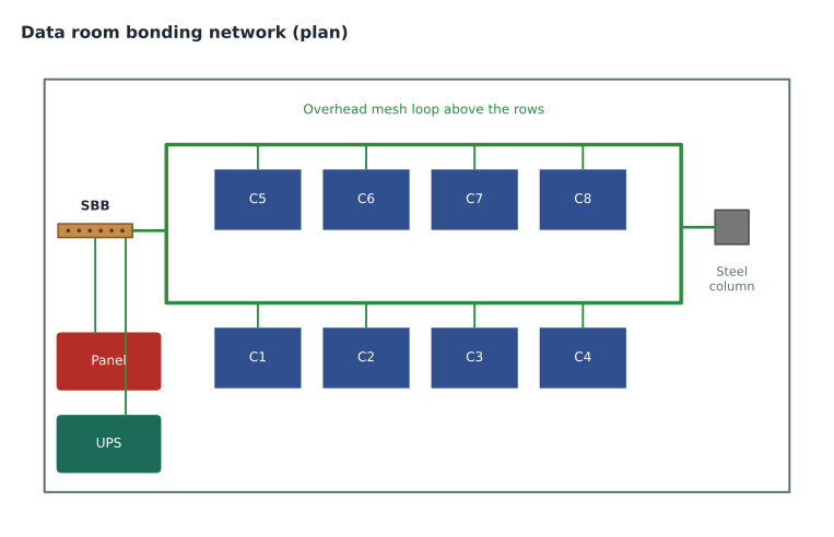
For rooms with more than a few cabinets, designers build a mesh bonding network: a grid of bare or insulated copper conductors, typically overhead above the cabinets or below a raised floor, bonded to the SBB and to building steel at several points. Each cabinet is bonded to the nearest mesh conductor with a short tap. The mesh gives many parallel paths across the room, so the impedance between any two cabinets is low, and it is easy to extend when cabinets are added.
Daniel's design for the data room used an overhead mesh. A single conductor ran above each row of cabinets, bonded to the SBB at one end and to the room's steel column at the other, and the two row conductors were tied together at both ends to form a rectangle. Each cabinet's rack bonding conductor tapped to the row conductor directly above it, and the cable ladder was bonded to the mesh at every section joint.
Racks and cabinets
A rack or cabinet is the meeting point for the metal frames of the equipment mounted in it, the cables that connect to that equipment and, often, the cable management and power strips on its sides. Bonding the rack puts all of those at the same potential and connects them to the room's network.
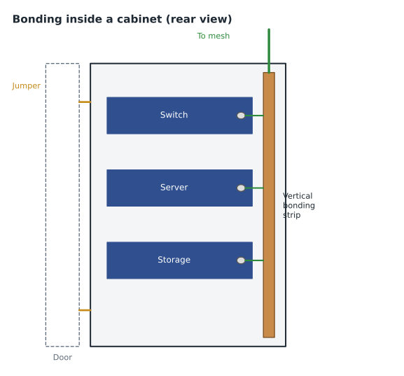
A rack bonding busbar or a vertical bonding strip runs the height of the rack, usually on the rear rail or the side of the frame. The rack bonding conductor connects that busbar to the SBB or the mesh. Where racks are in a row, each should have its own conductor to the SBB or mesh. Daisy-chaining, running a single conductor from rack to rack and then to the SBB, is not acceptable under current practice, because removing one rack breaks the bond for every rack downstream and because the chain concentrates current through each link.
Racks are painted or powder-coated, and paint is an insulator. Each section of a bolted rack must be bonded across its joints, and every connection to the rack must break through the paint. Rack makers supply bonding kits with thread-forming screws, star or serrated washers that bite through the coating, or jumpers that bridge assembled sections. Bolting a rack's top and side panels together with ordinary hardware does not bond them reliably. Roz's specification required the rack maker's bonding kit on every rack and a two-point resistance test after assembly, covered in lesson 12.
Cabinet doors and side panels often hang on hinges that make poor electrical contact. Bonding jumpers from doors and panels to the frame are inexpensive and keep the whole enclosure at one potential, which matters for both safety and the shielding the enclosure provides to the equipment inside.
| Part | How to bond it | What to avoid |
|---|---|---|
| Rack or cabinet frame | Rack bonding conductor from its busbar or strip to the SBB or mesh | Daisy-chaining several racks on one conductor |
| Bolted rack sections | Maker bonding kit or jumper across each joint | Relying on painted bolted joints |
| Cabinet doors and side panels | Flexible bonding jumpers to the frame | Assuming hinges provide a bond |
| Equipment chassis | Maker bonding point to the rack busbar or strip, or thread-forming mounting screws | Relying only on the power cord |
| Power distribution unit in the rack | Its own grounding through the power cord, plus bonding to the rack where the maker provides a point | Lifting the ground pin to cure noise |
Equipment bonding
Network switches, servers and other equipment have a metal chassis that is connected to the equipment grounding conductor in the power cord. Many also have a separate bonding point, usually a threaded stud or a pair of holes for a two-hole lug on the rear panel. Where a maker provides a bonding point, the installer should use it, connecting it with a short unit bonding conductor to the rack busbar. This gives the chassis a short, direct path to the rack that does not depend on the power cord or on the paint under its mounting ears.
Where no bonding point exists, mounting the equipment with thread-forming screws or serrated washers through the rack rails provides a reasonable bond, provided the rails are bonded to the rack frame. Equipment that is powered over Ethernet or from a DC plant may need its own consideration; a DC power system has its own return and bonding scheme, and the maker's instructions and the standard's provisions for DC systems govern.
Pathways: cable ladder, tray and raised floor
Cable ladder and cable tray are long runs of metal that pass through many spaces. If they are not bonded, they can carry surge or fault current along uncontrolled paths or float at a different potential from the racks they connect to. Each section of ladder or tray should be bonded to the next with a bonding jumper unless the maker's splice hardware is listed for bonding, and the run should be bonded to the SBB in each room it enters.
In the data room, Daniel bonded the overhead ladder to the mesh at each joint, which also served as the ladder's section-to-section bond. In the telecommunications rooms, he bonded the ladder to the SBB with one conductor and called for listed bonding splice plates at each joint. Where a tray leaves a room through a wall, the specification called for a bond on each side, so that a later change to one room would not leave the other with an unbonded section.
A raised floor's pedestals and stringers form a metal grid that can itself become part of the bonding network. Where a raised floor is used, designers typically bond a selection of pedestals to a mesh conductor run under the floor, often every second or third pedestal in each direction, and treat the floor grid as part of the mesh. Harbourview's data room is on a slab with overhead distribution, so the question did not arise, but Daniel noted the approach for the exam.
Shielded cabling
Most cabling at Harbourview is unshielded twisted pair, but the college's teaching lab includes a small amount of shielded Category 6A cabling for high-noise equipment, and the antenna systems use coaxial cable with metallic shields. A shield works only if it is bonded. At the telecommunications room end, a shielded cable's shield connects through the shielded patch panel to the rack, and through the rack to the SBB. At the work area end, the shield connects through the shielded outlet and equipment cord to the equipment, which is grounded through its power cord.
Because a shield is bonded at both ends, it can carry current if the two ends are at different potentials. That is the reason a good bonding network matters even more with shielded cabling: by keeping the potentials close, it keeps shield currents small. A designer who is worried about shield currents should improve the bonding, not cut the shield at one end, which would leave it unable to do its job at high frequencies and could leave the far end of the shield at a dangerous voltage.
Electrostatic discharge
Electrostatic discharge, the spark when a charged person touches equipment, can damage electronics without ever being noticed. In equipment rooms, technicians should use wrist straps connected to a bonded point on the rack when handling circuit boards, and racks should have a labelled ESD jack for that purpose. Floors with dissipative finishes help in larger rooms. The bonding network makes ESD protection possible: a wrist strap is only as good as the bond behind the jack it plugs into.
Beyond the equipment room
Bonding does not stop at the door of the telecommunications room. Metal enclosures for consolidation points and zone cabling, wall-mounted cabinets in ceilings or corridors, and the cabinets for distributed antenna system remote units all hold equipment and terminate cables, and each should be bonded. Where such an enclosure is far from a telecommunications room, the usual approach is a bonding conductor run with the horizontal cabling back to the SBB of the serving room, or a connection to a nearby electrical panel's equipment ground bus where the code and the design allow it.
Harbourview has six ceiling-mounted zone enclosures for the open office area on level 3, each holding a small switch for wireless access points and building sensors. Daniel ran a 6 AWG bonding conductor from each zone enclosure back to the TR-3 SBB alongside the cable bundle, rather than relying on the power circuit feeding the small switch. 'If it holds active equipment and terminates copper,' Roz said, 'treat it like a little telecommunications room.'
Equipment powered from a DC plant, common in carrier equipment and some radio systems, needs one extra check. A DC system has a return conductor that is normally bonded to the bonding network at one point, often at the DC plant itself, and the equipment frames are bonded separately. The maker's instructions and the DC provisions in the bonding standard decide where that point is. Bonding the DC return at several points creates paths for DC current through the bonding network, which corrodes connections over time.
The telecommunications rooms
TR-1 to TR-4 at Harbourview each hold two racks, a wall-mounted cabinet for the building automation controllers and a small power panel. Daniel's layout was the same on every floor: the SBB on the wall beside the riser sleeves, a rack bonding conductor from each rack's vertical strip to the SBB, the cable ladder bonded to the SBB, the wall cabinet bonded to the SBB, and the panel's equipment ground bus bonded to the SBB with a 6 AWG conductor. The total run from the farthest rack to the SBB was about 3 metres.
Repeating the same layout on every floor helped everyone. The installers built one floor and then repeated it, the inspection checklist was the same for each room and the as-built drawings were easy to check. Roz called it 'boring on purpose'.
Worked problem
Correcting a daisy chain
In the existing clinic building, the four racks in the second-floor telecommunications room were connected in a chain: rack A to rack B to rack C to rack D, and then from rack D to a water pipe. Describe what was wrong and how Daniel recommended fixing it.
Show solution
- The chain made every rack depend on every connection upstream of it. Removing or loosening one link would leave the racks beyond it unbonded.
- The water pipe was not a reliable reference, because parts of it had been replaced with plastic.
- The racks were painted, and the chain connections used ordinary bolts, so even the connections that existed were poor.
- Fix: install an SBB in the room, bonded to a new TBB from the building PBB; run a separate rack bonding conductor from each rack to the SBB; fit the rack maker bonding kits; bond the cable ladder to the SBB; and test each rack after the work.
Answer: Replace the chain with individual conductors from each rack to a new SBB connected to the building PBB, with proper paint-piercing hardware.
Common mistakes
MistakeDaisy-chaining racks on one bonding conductor.
InsteadRun a separate bonding conductor from each rack to the SBB or mesh.
MistakeRelying on painted bolted joints in a rack.
InsteadUse the maker's bonding kit or paint-piercing hardware at every joint and connection.
MistakeIgnoring the equipment bonding stud.
InsteadConnect the maker's bonding point to the rack busbar with a short unit bonding conductor.
MistakeCutting a cable shield at one end to cure noise.
InsteadImprove the bonding network so that potentials and shield currents are small.
Summary and key terms
- Small rooms bond each rack and the ladder to the wall SBB; larger rooms use a mesh bonding network tied to the SBB and steel.
- Each rack or cabinet gets its own bonding conductor; daisy-chaining is not acceptable.
- Paint insulates; bonded joints need the maker's bonding kit or paint-piercing hardware.
- Use the equipment maker's bonding stud with a short unit bonding conductor.
- Bond every section of cable ladder and tray, and bond the run to the SBB in every room it enters.
- Shields are bonded at both ends; good bonding keeps shield currents small.
- Mesh bonding network
- A grid of bonding conductors across an equipment room, tied to the SBB and building steel.
- Rack bonding conductor
- The conductor from a rack busbar or strip to the SBB or mesh.
- Unit bonding conductor
- A short conductor from an equipment bonding point to the rack busbar.
- Daisy chain
- A single conductor run from one rack to the next and then to a busbar.
- Electrostatic discharge (ESD)
- A sudden discharge of static charge that can damage electronics.
Practice problems
Work each problem on paper first, then reveal the answer to check.
Why is daisy-chaining racks not acceptable?
Show answer
Removing or loosening one link leaves every rack downstream unbonded, and the chain concentrates current.
What does a mesh bonding network provide that a single wall busbar does not?
Show answer
Many short parallel paths across the room, giving low impedance between any two cabinets.
How should a cable shield be treated if shield current causes noise?
Show answer
Improve the bonding so the ends are closer in potential; do not cut the shield.
What must an ESD wrist strap connect to?
Show answer
A bonded point on the rack, such as a labelled ESD jack.
Lesson quiz · 5 questions
Score 60% or more to complete this lesson.
Create a free account to save your progress, take quizzes and earn a certificate.