
RCDD-113 · Lesson 4 of 12 · 20 min
Busbars, bonding conductors and sizing principles
▶ Video coming soon A video version of this lesson is on the way.
Once the busbar schedule was agreed, Daniel had to specify the hardware: what the busbars are made of and how big they are, what kind of conductor the TBB and TBC use, how each connection is made and how large each conductor must be. 'This is where the drawings become a bill of materials,' Roz said. 'And it's where most value engineering arguments start. Someone will ask why a bonding conductor needs to be as big as a feeder. You need to be able to answer.'
Busbars
A busbar is a solid bar of copper with pre-drilled holes, mounted on insulated standoffs so that it is electrically separated from the wall or rack it is mounted on. The insulation is not there to isolate the busbar from the building; the busbar is bonded to the building on purpose. It is there so that the only connections to the busbar are the ones the designer intended and the installer can see and label.
Busbars are normally electrotin-plated copper, which resists corrosion and gives a consistent contact surface. Their size is set by the standard and by the number of conductors they must accept. Specifications commonly call for the PBB to be at least about 6 mm thick and 100 mm wide, and for an SBB to be at least the same thickness and about 50 mm wide, with lengths chosen to give room for every conductor in the design plus spare holes for growth. The designer should confirm the current minimum dimensions in ANSI/TIA-607 and CSA T527 rather than relying on a past project's details.
The holes are drilled in pairs to accept two-hole compression lugs, with spacing that matches standard lug patterns. Two-hole lugs are preferred because they cannot rotate and loosen the way a single-bolt connection can. The standoffs typically hold the busbar about 50 mm off the wall, enough for a hand and a wrench behind the conductors.
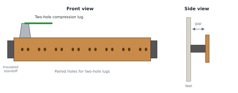
Daniel counted the conductors for each busbar before choosing lengths. The PBB had to accept the TBC, the TBB, the entrance protector bonding conductors for the service provider and campus cables, bonds to building steel and the water pipe, the cable ladder, the racks in the main equipment room and the room's electrical panel. That came to fourteen conductors at the start, and he chose a length with capacity for at least that many again. Busbars are cheap; replacing one later because it is full means taking every conductor off and putting it back.
Bonding conductors
Bonding conductors in a telecommunications bonding network are copper, normally stranded for flexibility and insulated. The insulation prevents accidental contact with other metal along the route, which would create uncontrolled paths, and it makes the conductor easy to identify. Standards and owner specifications typically call for a green jacket, or green with a yellow stripe, and for the conductor to be labelled at each end.
Where bonding conductors run in cable spaces that carry air for heating or cooling, the insulation must have the right fire rating, just as data cables do. A plain building wire with a thermoplastic jacket may not be acceptable in a plenum. Daniel's specification called for listed or certified insulated conductors suitable for the spaces they pass through, with the fire rating checked for each route.
A bonding conductor should be continuous between terminations. It should not be spliced except where the standard allows and with an irreversible connector. It should be as short and straight as practical, with sweeping bends rather than sharp ones, and it should not be bundled tightly with power cables. Where a bonding conductor passes through a metal conduit, the conduit must be bonded to the conductor at both ends; otherwise the steel acts as a choke around the conductor and raises its impedance at high frequencies.
Connections
Every connection in the network is a possible point of failure. A loose lug or a corroded joint adds resistance that grows over time and can fail completely during a surge, just when it is needed. Good practice is to use irreversible compression connectors, crimped with the tool and die that the maker specifies, or exothermic welds for conductors connected to building steel or below grade. Mechanical connectors are acceptable for some equipment connections where the equipment maker provides them, but they need periodic inspection.
Before a lug is bolted to a busbar, the contact surfaces should be clean, and an antioxidant compound is commonly applied. Bolts, nuts and washers should be of a corrosion-resistant metal compatible with copper. Where a bonding conductor connects to a painted surface, such as a rack or a steel column, the paint must be removed at the contact point or a connector with teeth that cut through paint must be used. Lesson 5 covers rack bonding hardware in more detail.
| Connection type | Typical use | Strengths | Cautions |
|---|---|---|---|
| Irreversible compression lug | Conductors to busbars | Consistent, low resistance, cannot loosen | Must use the specified tool and die |
| Exothermic weld | Conductors to building steel, ground rings, conductors to each other | Permanent molecular bond | Needs trained installers and fire precautions |
| Irreversible compression tap (H-tap or C-tap) | TBB tap to an SBB | Continuous backbone with a reliable branch | Tap size must match both conductors |
| Mechanical clamp | Bonding to pipes or where the maker supplies it | Simple to install and remove | Can loosen; needs periodic inspection |
| Paint-piercing hardware | Bonding racks and painted metal | Reliable contact through paint | Must be the correct type and torque |
Bonding to building steel and piping
Busbars are bonded to accessible structural steel in the room wherever the steel is part of the building frame and is itself bonded to the grounding electrode system. The connection is usually an exothermic weld or a listed clamp to a cleaned flange, with a short conductor of the same size as the rack bonds or larger. The value of the steel is that it is everywhere: a well-bonded frame provides many parallel paths between floors, which lowers the impedance between SBBs even though the TBB remains the designed path.
Metal water piping is treated with more caution. A metal water pipe that runs underground may be part of the grounding electrode system, and the code requires interior metal piping to be bonded, but pipes are replaced and repaired over a building's life, often with plastic sections, by people who have no idea they are part of an electrical system. The existing clinic building's protector was bonded to exactly such a pipe. Daniel's specification allowed a bond from the PBB to the metal water service pipe as a supplementary connection near its entry, and never as the only path.
Sizing principles
How big should the TBB be? The intuitive answer is that it must carry fault or surge current, but that is only part of the story. The TBB is not intended to carry large fault currents for long periods; the electrical system's equipment grounding conductors do that. Its main job is to keep the SBBs close in potential to the PBB, which means its impedance must be low. Longer conductors have higher impedance, so the TBB's size increases with its length.
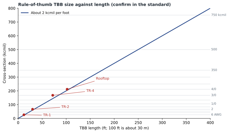
ANSI/TIA-607 gives a table of TBB sizes by length, with a minimum size of 6 AWG and a maximum of 750 kcmil. Commentaries on the standard describe the table as following roughly 2 kcmil of cross-section for every foot of length, which is about 6.6 kcmil for every metre. A designer should take the size from the current table in the standard; the rule of thumb is useful for checking a drawing or explaining why a long run gets a large conductor.
The TBC must be at least as large as the largest TBB it serves. If several TBBs start at one PBB, the TBC is sized to the biggest of them. BBCs are sized to match the TBBs they interconnect. Other bonding conductors, such as those from racks to the SBB or from protectors to the PBB, are typically 6 AWG minimum, subject to code requirements and to the maker's instructions for protectors.
Daniel measured the Harbourview TBB route on the sections. From the PBB to the SBB in TR-4, the conductor runs about 22 metres, and the continuation to the rooftop antenna enclosure adds another 9 metres. The data room tap on level 2 is a short branch. He wrote a short program to apply the rule of thumb to each length, then checked the results against the table in his copy of the standard.
# Rule-of-thumb TBB size: about 2 kcmil per foot of length, minimum 6 AWG, maximum 750 kcmil.
# Always confirm against the current ANSI/TIA-607 table; this only checks the order of magnitude.
SIZES = [("6 AWG", 26.24), ("4 AWG", 41.74), ("3 AWG", 52.62), ("2 AWG", 66.36), ("1 AWG", 83.69),
         ("1/0", 105.6), ("2/0", 133.1), ("3/0", 167.8), ("4/0", 211.6), ("250 kcmil", 250),
         ("300 kcmil", 300), ("350 kcmil", 350), ("500 kcmil", 500), ("750 kcmil", 750)]
def tbb_size(feet):
    need = 2.0 * feet
    for name, kcmil in SIZES:
        if kcmil >= need:
            return name, round(need)
    return "750 kcmil (maximum)", round(need)
runs = {"PBB to TR-1": 12, "PBB to TR-2": 30, "PBB to TR-4": 72, "PBB to rooftop SBB": 102}
for run, ft in runs.items():
    name, need = tbb_size(ft)
print(f"{run:20s} {ft:4d} ft need ~{need:4d} kcmil -> {name}")PBB to TR-1 12 ft need ~ 24 kcmil -> 6 AWG PBB to TR-2 30 ft need ~ 60 kcmil -> 2 AWG PBB to TR-4 72 ft need ~ 144 kcmil -> 3/0 PBB to rooftop SBB 102 ft need ~ 204 kcmil -> 4/0
The longest run, to the rooftop enclosure, sets the size of the TBB, because the TBB is one continuous conductor from the PBB to its farthest SBB. A designer can sometimes reduce the size by giving the rooftop SBB its own TBB from the PBB, but on Harbourview the single run up the core was simpler, and the extra copper was a small cost. The TBC was then sized to match the TBB. Daniel noted that the result is larger than the conductors in the existing clinic building's owner standard, which called for 6 AWG throughout, a size the standard now allows only for short runs.
Labelling
Every busbar and every bonding conductor should be labelled. ANSI/TIA-606, the administration standard, gives an identifier scheme for bonding parts, and the bonding standard requires labels at each end of conductors such as the TBC and TBB. A common label on the TBC at the service end warns that the conductor must not be disconnected without first contacting the telecommunications manager. Lesson 12 covers the labels and records in detail.
Labels serve the people who maintain the building twenty years from now. A green conductor that disappears into a ceiling is a mystery to the next electrician; a labelled one is a known part of a documented system. Roz had seen too many unlabelled bonding conductors cut by renovation crews who assumed they were abandoned.
Answering the value engineering question
At the design review, the general contractor's project manager, Marcus Feld, raised the question Roz had predicted. 'The TBB is a 4/0 conductor. That's the size of a feeder. It doesn't carry any load. Can we drop it to 6 AWG like the old building?' Daniel had prepared an answer. The TBB's job is to keep potential differences small during surges and faults, which depends on low impedance over its length. The size comes from the standard that the owner's contract requires. The old building's 6 AWG conductors were part of the reason its second-floor equipment failed in the storm. And the difference in material cost for the run was smaller than the cost of replacing a single network switch.
Marcus accepted the answer but asked that the specification state the standard and revision clearly, so that his subcontractors could not argue about it later. That was a good outcome: a specification that names the governing standard is easier to enforce than one that states sizes without saying where they came from.
Worked problem
Sizing the conductors at Harbourview
The TBB runs 102 feet from the PBB to the rooftop SBB, with taps to SBBs on each floor along the way. One TBB serves the building. Using the rule of thumb, find the TBB and TBC sizes, and say what the rack and protector bonding conductors should be.
Show solution
- Required cross-section is about 2 kcmil per foot: 2 × 102 = 204 kcmil.
- The next standard size at or above 204 kcmil is 4/0 AWG, at 211.6 kcmil.
- The TBC must be at least as large as the largest TBB: 4/0 AWG.
- Rack and protector bonding conductors are typically 6 AWG minimum, subject to the code and the protector maker.
- Confirm all sizes against the current ANSI/TIA-607 table before issuing the drawings.
Answer: TBB 4/0 AWG, TBC 4/0 AWG, rack and protector bonds 6 AWG minimum, confirmed against the standard.
Common mistakes
MistakeMounting a busbar directly on a steel wall.
InsteadMount busbars on insulated standoffs so that every connection is intentional and visible.
MistakeUsing single-hole lugs on busbars.
InsteadUse two-hole compression lugs that cannot rotate and loosen.
MistakeRunning a bonding conductor through steel conduit without bonding the conduit.
InsteadBond ferrous conduit to the conductor at both ends.
MistakeSizing every bonding conductor at 6 AWG regardless of length.
InsteadSize the TBB by length from the standard's table; the TBC matches the largest TBB.
Summary and key terms
- Busbars are tin-plated copper on insulated standoffs, drilled for two-hole lugs, with spare capacity.
- Bonding conductors are insulated stranded copper, labelled at both ends and rated for the spaces they pass through.
- Use irreversible compression connectors or exothermic welds; avoid splices.
- Bond ferrous conduit to the bonding conductor at both ends.
- TBB size grows with length; the standard's table runs from 6 AWG to 750 kcmil, roughly 2 kcmil per foot.
- The TBC is at least as large as the largest TBB.
- Two-hole lug
- A compression lug fastened with two bolts so that it cannot rotate.
- kcmil
- Thousands of circular mils, a unit of conductor cross-section used for large conductors.
- Choke effect
- The increase in impedance when a conductor passes through an unbonded ferrous enclosure.
- Antioxidant compound
- A paste applied to electrical joints to prevent oxidation of the contact surfaces.
- Standoff
- An insulating support that holds a busbar away from the wall.
Practice problems
Work each problem on paper first, then reveal the answer to check.
Why are busbars mounted on insulated standoffs?
Show answer
So that the only connections are intentional, visible and labelled.
What is the rule of thumb for TBB size?
Show answer
About 2 kcmil per foot of length, within 6 AWG to 750 kcmil; confirm with the standard's table.
How is the TBC sized?
Show answer
At least as large as the largest TBB it serves.
Why bond steel conduit at both ends of a bonding conductor?
Show answer
To prevent the conduit acting as a choke that raises the conductor's impedance.
Lesson quiz · 5 questions
Score 60% or more to complete this lesson.
Create a free account to save your progress, take quizzes and earn a certificate.