
RCDD-113 · Lesson 12 of 12 · 20 min
Inspecting and documenting bonding and protection
▶ Video coming soon A video version of this lesson is on the way.
Harbourview's construction ran through the winter. By April the TRs had their racks, the riser had its backbone cables and the TBB, and the PBB in the entrance facility was full of green conductors. Daniel spent two days on site with Tomasz Wiercinski walking every telecommunications space with a checklist, a low-resistance ohmmeter and a camera. 'This is the part people skip,' Roz had told him. 'The design is only a promise. Inspection and documentation are how you find out whether the building keeps it, and how the next person knows what's there.'
This lesson covers the final stage: inspecting the installed bonding and protection system, testing it, labelling it, recording it and planning its maintenance. It ends with the Harbourview commissioning report and with what happened at the existing clinic building the following summer.
Inspect before it is hidden
Bonding conductors run through ceilings, shafts and walls that will be closed. Connections to building steel are often made before fireproofing is sprayed. The single most useful inspection habit is to look at work before it disappears. Daniel's construction schedule included hold points: the TBB in the riser before the shaft walls were closed, the connections to steel before fireproofing, and the PBB and protector field before the entrance facility backboard was crowded with equipment. At each hold point, Tomasz's crew called Daniel, who inspected, photographed and released the work.
Photographs are cheap and permanent. A photo of each connection to steel, each TBB tap and each busbar with its labels visible, filed by location, answers questions years later that no drawing can. Roz's office kept them with the project records and gave a copy to the owner.
The visual inspection checklist
A visual inspection checks that what was designed was installed, and installed properly. Daniel's checklist for each space followed the order of the bonding path, from the busbar out to the equipment.
| Item | Check |
|---|---|
| Busbar | Correct type and size; on insulated standoffs; mounted at the designed location; spare holes available; labelled |
| TBB and TBC | Correct size; continuous; no splices except approved irreversible ones; sweeping bends; ferrous conduit bonded at both ends; labelled at each end |
| Connections | Two-hole compression lugs or exothermic welds; correct tool marks on crimps; antioxidant applied; hardware tight; paint removed or paint-piercing hardware used |
| Racks and cabinets | Each rack has its own bonding conductor; maker bonding kit installed; doors and panels jumpered; ESD jack present |
| Pathways | Ladder and tray bonded across joints and to the SBB in each room |
| Protectors | Located near the cable entry; short straight bond to the PBB; units installed; armour and shields bonded |
| SPDs | Installed at the designed locations; short leads; status indicators normal; ground terminals bonded |
| Power | TR panel ground bus bonded to the SBB; receptacles and circuits as designed; no neutral-to-ground bonds downstream of the service |
In TR-3, the inspection found two problems. The cable ladder had been extended after the original installation to reach a new rack, and the new section had no bonding jumper. And one rack's bonding conductor had been landed on the SBB with a single-hole lug, because the installer had run out of two-hole lugs. Both were fixed the same day. On level 4, the TBB tap to the SBB had been made with a mechanical split-bolt connector instead of the specified irreversible compression tap. Tomasz had it replaced.
Testing the bonding network
Visual inspection finds missing and poorly made connections. Testing measures whether the connections that exist are good. Two kinds of test are used for ICT bonding networks.
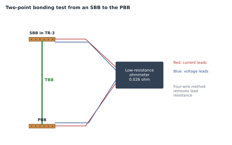
The first is the two-point bonding test, sometimes called a continuity or bonding resistance test. A low-resistance ohmmeter, often a four-wire instrument that can measure in milliohms, is connected between two points that should be well bonded: an SBB and the PBB, a rack and its SBB, two sections of cable ladder. The reading shows the resistance of the bonding path between them. A good path gives a very low value; a poor or missing connection gives a high one. ANSI/TIA-607 discusses testing, and owners commonly set maximum values in their standards, for example a fraction of an ohm between any SBB and the PBB. The Harbourview specification set its limits in the owner's terms and required every SBB, every rack and every ladder run to be tested.
The test has a limitation: it measures resistance at DC or low frequency, not impedance at surge frequencies. A long, looping conductor can test perfectly and still perform poorly in a surge. That is why visual inspection of routing remains essential, and why the design rules for short, straight conductors matter even though no simple field test checks them.
| Test point | Reading | Result |
|---|---|---|
| SBB TR-1 | 12 mΩ | pass |
| SBB TR-2 | 19 mΩ | pass |
| SBB TR-3 | 26 mΩ | pass |
| SBB TR-4 | 38 mΩ | pass |
| SBB data room | 21 mΩ | pass |
| SBB rooftop | 61 mΩ | pass |
| Rack TR-3 R1 | 8 mΩ | pass |
| Rack TR-3 R2, before fix | 940 mΩ | fail |
| Rack TR-3 R2, after fix | 9 mΩ | pass |
| Rack DR C1 | 6 mΩ | pass |
| Rack DR C8 | 11 mΩ | pass |
The results show the pattern Daniel expected. SBB readings rise with distance from the PBB, because the TBB's resistance grows with its length, and all were well within the owner's limit. One rack in TR-3 failed at first: the single-hole lug found in the visual inspection had been left loose. After the lug was replaced and torqued, the rack tested at 9 milliohms. A test that finds nothing wrong is reassuring; a test that finds the fault an inspection already suspected confirms both methods.
The second kind of test is a ground resistance test of the building's grounding electrode system, which measures the resistance between the electrodes and remote earth, typically by the fall-of-potential method or with a clamp-on tester. That test belongs to the electrical system and is the electrical engineer's and electrical contractor's responsibility. The RCDD should obtain the result for the project records, because it explains how high the building will rise in a strike, but should not confuse it with the bonding tests.
Labels
ANSI/TIA-606, the administration standard, defines identifiers for telecommunications infrastructure, including bonding parts. Each busbar gets an identifier tied to its space; each bonding conductor gets an identifier showing what it connects. Labels must be durable, legible and placed where they can be seen without disturbing the installation. The TBC and the TBB are labelled at each end with a warning that the conductor must not be disconnected without contacting the person responsible for the telecommunications infrastructure.
At Harbourview the PBB was labelled with its identifier, the date of installation and a small plaque explaining what it was, because the facilities staff were not ICT specialists. Every conductor on the PBB carried a label at the busbar end showing its far end: 'TBB to TR-1, TR-2, TR-3, TR-4, rooftop', 'TBC to MDP ground bus', 'Protector, provider copper'. Tomasz's crew used printed wrap-around labels rated for the environment.
| Part | Example identifier | Label location |
|---|---|---|
| Primary bonding busbar | PBB 1-EF | On the busbar and on a plaque above it |
| Secondary bonding busbar | SBB 3-TR3 | On the busbar |
| Telecommunications bonding conductor | TBC PBB 1-EF to MDP | At each end, with a do-not-disconnect warning |
| Telecommunications bonding backbone | TBB PBB 1-EF to SBB 5-ROOF | At each end and at each tap |
| Rack bonding conductor | RBC 3-TR3-R2 | At the rack and at the SBB |
Records
The records for the bonding and protection system are part of the building's telecommunications documentation. They should include as-built drawings showing every busbar, conductor and connection to steel; the busbar schedule with the conductors on each busbar; the protector and SPD inventory with locations, makes and models; the test results; the photographs; the written answers from the AHJ; and the maintenance plan. ANSI/TIA-606 describes records and reports in general terms, and owner standards often set the format.
Roz insisted that the records be handed over in a form the owner could actually use: drawings in the owner's CAD standard, a spreadsheet of busbars and conductors keyed to the labels, and a single summary document that a new facilities manager could read in twenty minutes. The test reports went in an appendix.
Maintenance
A bonding and protection system needs care. Connections loosen with vibration and temperature cycles, corrosion builds in damp spaces, protector units wear out after surges, SPDs degrade, and renovations add racks and ladder sections without bonding them. Daniel's maintenance plan for Harbourview set out an annual inspection of every busbar and a sample of rack bonds, retesting of SBB-to-PBB resistance every few years, inspection of protectors and SPD status indicators after every major storm and at least yearly, and a requirement that any change to a telecommunications space include bonding of new racks and pathways, tested and recorded.
The plan also named a person. Bonding systems fail through neglect when nobody is responsible for them. The clinic group appointed its IT infrastructure manager as the owner of the telecommunications bonding system, with the facilities manager responsible for the electrical side, and both names went on the PBB plaque.
Renovations deserve their own rule. Most bonding failures in older buildings were not design errors but changes made years later by people who did not know the system existed: a rack added and never bonded, a ladder extended, a TBB cut during a ceiling replacement. Daniel added a one-page bonding requirement to the clinic group's standard for tenant and renovation work, so that every future project touching a telecommunications space would bond, test and record its changes.
Commissioning the whole system
Commissioning tests the system as a whole. For bonding and protection, that meant confirming the inspections and tests above, verifying that SPD status contacts reported to the building management system and, with Priya, running a planned power test: the utility supply to the building was opened during a weekend window, the UPS systems carried the data room and TRs, the generator started and the transfer switches moved the loads. Every switch and server was monitored for resets. None occurred. The generator ran under load for an hour, the utility was restored and the loads transferred back.
Daniel wrote the commissioning summary for the bonding and protection system in two pages: what was installed, what was found and fixed, the test results, the open items (none) and the maintenance plan. Roz reviewed it, signed it as the responsible RCDD, and, for the first time on a project, added Daniel's name beside hers as the designer.
The following summer
In July, a storm stronger than the one that had started the project crossed the lake. The existing clinic building had been retrofitted the previous autumn using the lessons of this course: a new PBB beside its service with a proper TBC, a short protector bond, an SBB and TBB to the second-floor TR, individual rack bonding conductors and all-dielectric fibre on the campus link. Harbourview was open and running.
On Monday morning, the facilities manager called Roz. Nothing had failed in either building. The SPD monitoring at Harbourview showed that the Type 1 device at the main switchboard had operated several times during the night and that two of the outdoor camera SPDs had registered surges. The switches had logged nothing unusual. The nurse call system had not rebooted. 'That,' Roz told Daniel, 'is what a good bonding design looks like from the outside. Nothing happens.'
Worked problem
Writing a test acceptance statement
Using the Harbourview test results in the table, write the statement Daniel would include in the commissioning summary.
Show solution
- List the test method: four-wire low-resistance ohmmeter, two-point bonding test.
- State the limits from the owner standard: 100 milliohms from any SBB to the PBB and 50 milliohms from any rack to its SBB.
- Summarize the results: SBB readings from 12 to 61 milliohms, all within the limit; rack readings from 6 to 11 milliohms after one correction.
- Record the correction: TR-3 rack R2 initially read 940 milliohms because of a loose single-hole lug; the lug was replaced with a two-hole compression lug and the rack retested at 9 milliohms.
- State acceptance: all tested bonds meet the owner standard.
Answer: All SBBs (12 to 61 milliohms) and racks (6 to 11 milliohms) passed the owner limits after one corrected connection in TR-3.
Common mistakes
MistakeInspecting after the ceilings are closed.
InsteadSet hold points to inspect and photograph bonding before it is hidden.
MistakeTreating a passing resistance test as proof of good surge performance.
InsteadCombine testing with visual inspection of routing, because DC tests do not measure surge impedance.
MistakeLeaving bonding conductors unlabelled.
InsteadLabel every busbar and conductor at each end, with warnings on the TBC and TBB.
MistakeHanding over records nobody can use.
InsteadProvide drawings, a busbar schedule, test results and a short summary in the owner's formats.
Summary and key terms
- Inspect and photograph bonding work at hold points before it is hidden.
- A visual checklist follows the bonding path from busbars to equipment, pathways, protectors, SPDs and power.
- Two-point bonding tests with a low-resistance ohmmeter measure the quality of connections against owner limits.
- DC tests do not measure surge impedance, so routing must still be inspected.
- Label every busbar and bonding conductor using ANSI/TIA-606 identifiers, with warnings on the TBC and TBB.
- Records, a maintenance plan and a named owner keep the system working; commissioning tests it as a whole.
- Hold point
- A stage in construction at which work stops until an inspection is done.
- Two-point bonding test
- A resistance measurement between two points of a bonding network using a low-resistance ohmmeter.
- Four-wire measurement
- A method using separate current and voltage leads to measure very low resistances accurately.
- Fall-of-potential test
- A method of measuring the resistance of a grounding electrode system to remote earth.
- ANSI/TIA-606
- The administration standard for telecommunications infrastructure, covering identifiers, labels and records.
- Commissioning
- Testing and verifying that a completed system works as designed.
Practice problems
Work each problem on paper first, then reveal the answer to check.
Why set hold points for bonding inspections?
Show answer
So bonding can be inspected and photographed before it is hidden.
What does a two-point bonding test measure?
Show answer
The resistance of the bonding path between two points.
Why can a bonding path pass a resistance test and still perform poorly?
Show answer
DC tests do not measure impedance at surge frequencies; long looping routes have high inductance.
Who should own the bonding system after handover?
Show answer
A named person, such as the IT infrastructure manager, with facilities responsible for the electrical side.
Lesson quiz · 5 questions
Score 60% or more to complete this lesson.
Create a free account to save your progress, take quizzes and earn a certificate.