
LVT-330 · Lesson 10 of 12 · 19 min
Bonding and grounding fundamentals
Few subjects in the low-voltage trade cause as much confusion as grounding. Installers hear that equipment must be grounded, that ground loops cause noise, that telecommunications needs its own clean ground, and that shielded cable must be grounded at one end or both ends, and many of those statements are half true at best. Greta asks Ravi Menon, the electrical contractor's foreman at Kellerman, to spend an afternoon with Maya on the subject before the riser bonding work starts. Ravi begins with two words that are often used as if they meant the same thing, and do not.
Grounding and bonding
Grounding is connecting something to the earth, through a grounding electrode such as a ground rod, a metal water pipe, the building's steel or a conductor encased in the foundation concrete. The earth connection holds the electrical system at a stable voltage relative to the ground people stand on, limits the voltage that lightning and power line surges can impose, and gives a path to earth for static and surge currents.
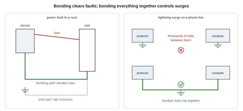
Bonding is connecting metal parts together with conductors so that they stay at the same voltage as each other. Bonding is what makes a building safe during a fault: if a power conductor touches a metal enclosure, the bonding conductors carry the fault current back to the source so that the breaker or fuse trips quickly, and while the fault lasts, all the bonded metal rises together, so a person touching two pieces of it feels no difference. Bonding is also what makes the building survive a surge: if every system's metal is bonded together, a lightning surge raises the whole building's potential at once instead of creating thousands of volts between the telephone wiring and the power wiring.
The key point, Ravi says, is that the earth is a poor conductor. A ground rod might have a resistance to earth of 25 ohms or more. A fault current of a few hundred amperes flowing through that would leave the equipment at thousands of volts and might not trip the breaker. Breakers trip because of bonding, the low-impedance path back to the source, not because of grounding. And two systems each connected to its own ground rod, but not bonded to each other, can be thousands of volts apart during a surge, because the earth between the rods is not a conductor.
The building's electrical grounding system
The electrical contractor builds the grounding system at the service under Section 10 of the electrical code. It has a grounding electrode, or several electrodes bonded together into a grounding electrode system; a grounding conductor from the service to the electrode; the bond between the neutral and the service enclosure at the service, and nowhere else; and bonding conductors that run with every circuit to bond the metal enclosures, raceways and equipment back to the service. Every other system in the building, including communications, connects to that one system. The CEC requires communication protectors, shields and the telecommunications bonding system to be bonded to it, not to separate electrodes of their own; where a separate electrode is used for some reason, it must itself be bonded to the building's grounding electrode system.
That one-system principle is the most important thing in this lesson. Telecommunications equipment does not need, and must not have, an isolated ground of its own that is not bonded to the power system. Some older installations had separate telecom ground rods, sometimes called clean grounds, connected to nothing else. They create exactly the voltage difference that destroys equipment and endangers people during a surge. Where Cobalt Line finds one in a renovation, it is reported and bonded to the building system.
Bonding conductors and impedance
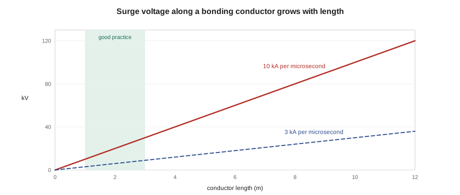
A bonding conductor must be large enough to carry the current that may flow in it without damage, and short and direct enough to keep its impedance low. For power faults, which last milliseconds to seconds at line frequency, the conductor's resistance is what matters, and copper size sets it. For lightning surges, which rise in a microsecond or so, the conductor's inductance matters much more, because the voltage across an inductance is proportional to how fast the current changes. A straight copper conductor has an inductance of roughly one microhenry per metre, and a lightning surge can change at ten thousand amperes per microsecond, so a single metre of conductor can develop thousands of volts during the surge's rise. That is why bonding conductors are kept short and straight, with gentle bends rather than sharp ones and no coils of spare length.
# Voltage across a copper bonding conductor: power fault (resistance) and surge front (inductance)
RHO = 1.724e-8                      # ohm-metre, copper at 20 C
AREA = {"6 AWG": 13.3, "2 AWG": 33.6, "1/0": 53.5, "3/0": 85.0}   # mm2
L_PER_M = 1.0e-6                    # henry per metre, rough value for a single straight conductor
length_m = 6.0                  # 6 m from protector to bonding point
fault_a = 2000                      # power fault current through the conductor, amperes
di_dt = 10e3 / 1e-6                 # surge front, 10 kA per microsecond
for size, a in AREA.items():
    r = RHO * length_m / (a * 1e-6)
    print(f"{size:6s} R = {r*1000:6.2f} milliohm   fault drop = {fault_a * r:5.1f} V")
v_surge = L_PER_M * length_m * di_dt
print(f"Surge front on {length_m:.1f} m of conductor: about {v_surge/1000:.0f} kV, whatever its size")6 AWG R = 7.78 milliohm fault drop = 15.6 V 2 AWG R = 3.08 milliohm fault drop = 6.2 V 1/0 R = 1.93 milliohm fault drop = 3.9 V 3/0 R = 1.22 milliohm fault drop = 2.4 V Surge front on 6.0 m of conductor: about 60 kV, whatever its size
The results make Ravi's point. During a power fault, even a modest conductor keeps the voltage drop to a few volts, and a larger one to a fraction of a volt. During the steep front of a lightning surge, the voltage depends on the length, not the size, and every metre adds kilovolts. Size is chosen for fault current and mechanical strength; length and routing are chosen for surges.
Ground loops and noise
A ground loop exists when two pieces of equipment are connected both by a signal cable with a shield or reference conductor and by their separate connections to the power ground, so that a loop of conductors is formed. If the two grounding points are at slightly different voltages, or a magnetic field passes through the loop, current flows in the cable shield or signal reference and can add hum to audio or noise to video. The fix is not to cut the bonding to make the ground isolated, which is unsafe, but to make the bonding better, so the two ends are at nearly the same voltage, and to use balanced, transformer-isolated or fibre connections for sensitive signals.
For balanced twisted-pair data cabling, ground loops are rarely an issue, because unshielded twisted pair has no shield and the transformers in each Ethernet port isolate the signal. For shielded twisted-pair and coaxial systems, the standards require the shield to be bonded at both ends through the patch panel and the equipment, with the panels bonded to the telecommunications bonding system. A well-bonded system with short, low-impedance connections keeps the voltage between the two ends small, so shield currents stay small too.
Grounding electrodes and resistance
The resistance of a building's grounding electrode system to earth depends on the soil, the electrodes and the weather. The electrical code sets the electrodes required; it does not make telecommunications contractors responsible for the electrode system. Some telecommunications and equipment specifications ask for a low resistance, often 5 ohms or less, and may require testing it. That test is normally done by the electrical contractor or a testing firm, using the fall-of-potential method or a clamp-on tester.
In a fall-of-potential test, a current is driven between the electrode under test and a remote current probe, and the voltage is measured to a potential probe placed at intervals between them. Dividing the voltage by the current gives a resistance at each position. The reading levels off on a plateau when the potential probe is outside the influence of both the electrode and the current probe, commonly near 62 per cent of the distance to the current probe for a simple electrode. If there is no plateau, the probes are too close together. Lesson 12's capstone includes reading such a test report.
# Fall-of-potential readings: find the plateau and the electrode resistance
readings = [  # (potential probe distance as % of current probe distance, measured ohms)
    (20, 2.1), (30, 2.9), (40, 3.4), (50, 3.6), (52, 3.7), (62, 3.8), (72, 4.0), (80, 4.6), (90, 6.2)]
def plateau(rows, window=3, tol=0.08):
    best = None
    for i in range(len(rows) - window + 1):
        vals = [r for _, r in rows[i:i + window]]
        spread = (max(vals) - min(vals)) / (sum(vals) / window)
        if spread <= tol and (best is None or spread < best[1]):
            best = (i, spread)
    return best
p = plateau(readings)
if p is None:
    print("No plateau: move the current probe further away and repeat")
else:
    i, s = p
    mid = readings[i + 1]
    print(f"Plateau around {mid[0]} %: electrode resistance about {mid[1]:.1f} ohm (spread {s*100:.0f} %)")
print("Specification limit 5.0 ohm ->", "OK" if mid[1] <= 5.0 else "too high: add or extend electrodes")Plateau around 52 %: electrode resistance about 3.7 ohm (spread 5 %) Specification limit 5.0 ohm -> OK
What the low-voltage installer bonds
On a typical job, Cobalt Line's bonding work is limited and clear, and it connects to the electrician's system at defined points:
- Primary protectors and cable shields at the entrance, bonded to the PBB in the entrance room or directly to the building's bonding point.
- The telecommunications bonding backbone and busbars described in lesson 11.
- Equipment racks, cabinets, cable trays and ladder racks in telecommunications rooms, bonded to the busbar in the room.
- Shielded cabling patch panels and equipment, bonded to the rack and so to the busbar.
- Metallic cable armour and conductive fibre cable members, at the points the code and standards require.
The electrician provides the connection to the electrical service: the bonding conductor from the main busbar to the service equipment or the intersystem bonding point, and the bond of the electrical panels serving each telecommunications room. The interface list from lesson 1 says who does what at each point.
Connections
A bonding system is only as good as its connections. The standards and good practice call for listed connectors: compression lugs crimped with the matching tool and die, two-hole lugs on busbars so they cannot rotate, exothermic welds or listed compression connectors for conductor splices and connections to building steel, and listed clamps for pipes. Paint and coatings must be removed under every lug, and an antioxidant compound applied where the manufacturer calls for it. Split bolts, self-tapping screws through painted metal and twisted wires are not acceptable connections for a bonding system.
Worked problem
A clean ground in the basement
Opening the old telephone room at Kellerman, Maya finds the original telephone protector panel grounded with a green conductor to a ground rod driven through the basement floor slab. Nothing connects that rod to the building's electrical grounding. The new PBB is being installed on the opposite wall.
Show solution
- The isolated rod creates a separate ground that can be thousands of volts from the power ground during a surge.
- The code requires a separate electrode used for communications to be bonded to the building's grounding electrode system.
- The protectors will be bonded to the new PBB, which is bonded to the electrical service.
- The old rod is either bonded to the building's grounding electrode system with a conductor of the required size, or abandoned and its conductor removed, as the electrical engineer decides.
Answer: The engineer decides to bond the rod rather than abandon it, since it adds an electrode to the system. Ravi installs the bond, and Maya records the change on the drawings and in the closeout report.
Ravi ends the afternoon with a short list for Maya's notebook: bond everything to one system; keep bonding conductors short and straight; size for fault current, route for surges; use listed connectors on clean metal; and never remove a bond to fix a noise problem.
Common mistakes
MistakeThinking the earth clears faults.
InsteadBonding back to the source clears faults; the earth is a poor conductor.
MistakeInstalling a separate, isolated ground for telecommunications.
InsteadBond every system to the one building grounding electrode system.
MistakeLeaving coils of spare bonding conductor.
InsteadCut to length and route short and straight; length adds surge voltage.
MistakeCutting a shield bond to cure hum.
InsteadImprove bonding, or use balanced, isolated or fibre connections; never remove safety bonds.
MistakeUsing split bolts or screws through paint.
InsteadUse listed lugs and connectors on clean metal.
Summary and key terms
- Grounding connects to earth; bonding connects metal parts together.
- Bonding clears faults and keeps metal at the same voltage; the earth alone cannot clear a fault.
- All systems bond to one building grounding electrode system; isolated telecom grounds are hazards.
- Resistance matters for power faults; inductance, and so length and routing, matters for surges.
- Ground loop noise is solved with better bonding and balanced or isolated connections, not by removing bonds.
- Fall-of-potential tests find the electrode resistance on a plateau of readings.
- Grounding
- Connecting a system to the earth through an electrode.
- Bonding
- Connecting metal parts so they stay at the same voltage and carry fault current.
- Grounding electrode system
- All the electrodes at a building bonded together.
- Ground loop
- A loop formed by a signal connection and two ground paths, which can carry noise current.
- Fall-of-potential test
- A three-point test that measures an electrode's resistance to earth.
- Inductance
- The property of a conductor that opposes changes in current; it sets surge voltage.
Practice problems
Work each problem on paper first, then reveal the answer to check.
Why does a breaker trip during a fault to a metal enclosure?
Show answer
Bonding gives a low-impedance path back to the source.
Why is an isolated telecom ground rod dangerous?
Show answer
During a surge it can be thousands of volts from the power ground.
What matters more for a surge: conductor size or length?
Show answer
Length and routing, because of inductance.
What does a missing plateau in a fall-of-potential test mean?
Show answer
The probes are too close; move the current probe further away.
Lesson quiz · 5 questions
Score 60% or more to complete this lesson.
Create a free account to save your progress, take quizzes and earn a certificate.