
FAT-340 · Lesson 5 of 12 · 21 min
Electrical theory and calculations review
Every fire alarm exam has calculation questions, and they are the ones candidates most often get wrong under time pressure. Not because the arithmetic is hard, but because the setup is: the wrong current for a strobe, the wrong length for a loop, the wrong standby time for the building. Gerry runs this session as a workshop. Sasha and Nadia each have a calculator, a pencil and a page of Gerry's problems, and they work every one by hand before checking it with the code below. 'On the exam you won't have the script,' he reminds them. 'You'll have the steps. Learn the steps.' This lesson reviews FAT-130: Ohm's law, series and parallel circuits, conductor resistance, power supplies, battery calculations and voltage drop on notification circuits.
Ohm's law and power
Voltage, current and resistance are related by Ohm's law, V = I R, and power by P = V I (FAT-130 lessons 2 and 3). In a series circuit the current is the same everywhere and the resistances add; in a parallel circuit the voltage is the same across each branch and the currents add. Fire alarm initiating circuits use end-of-line resistors so the panel can supervise the wiring: the panel sees a known resistance when the circuit is normal, a much lower resistance when a device shorts it into alarm, and an open circuit when a wire breaks (FAT-130 lesson 10).
Worked problem
A supervisory current
A conventional initiating circuit has a 4.7 kΩ end-of-line resistor and is powered at 24 V. What current flows when the circuit is normal, and what happens when a detector goes into alarm?
Show solution
- Normal: I = V / R = 24 V / 4,700 Ω = 0.0051 A, about 5.1 mA.
- In alarm, the detector places a low resistance across the circuit, so the current rises well above the supervisory level.
- The panel reads the change in current and indicates an alarm for that zone.
- If a wire breaks, the current falls to zero and the panel shows a trouble signal.
Answer: About 5 mA normally, higher in alarm, zero for an open. The trap is mixing up an open (trouble) with a short (alarm on a conventional circuit).
Conductor resistance
The resistance of a copper conductor depends on its size, length and temperature. FAT-130 lesson 5 gives the values commonly used: about 21 Ω per km for 18 AWG, 13.2 Ω per km for 16 AWG, 8.3 Ω per km for 14 AWG and 5.2 Ω per km for 12 AWG, per conductor. A circuit has two conductors, so the loop resistance is twice the one-way length times the resistance per metre. The trap is forgetting to double the length.
Voltage drop on notification circuits
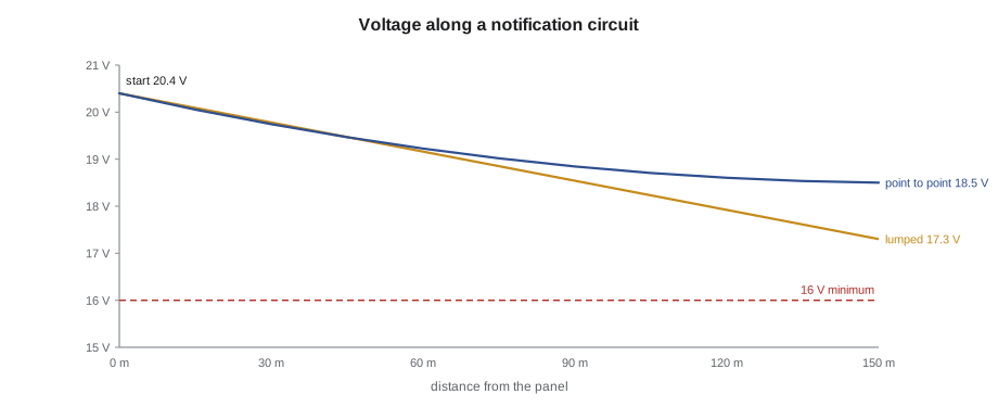
Notification appliances are listed to work over a voltage range; for 24 V nominal appliances, the regulated range is 16 to 33 V, and the current the manufacturer publishes is the maximum over that range (FAT-130 lesson 9). The designer must show that the last appliance on each circuit receives at least the minimum voltage, with the panel's output at its lowest, end-of-discharge battery voltage. The quick method treats the whole load as if it were at the end of the circuit, which is conservative. The point-to-point method calculates the drop on each segment and is more accurate on long circuits.
# NAC voltage drop: lumped load and point-to-point, starting at end-of-discharge voltage
r_per = 8.28           # ohms per km per conductor (14 AWG)
v_start = 20.4           # V, battery at end of discharge
segments = [(30, 0.25), (30, 0.25), (30, 0.25), (30, 0.25), (30, 0.25)]         # (length m, appliance current A) from the panel outward
total_i = sum(i for _, i in segments)
total_len = sum(l for l, _ in segments)
lumped = v_start - total_i * 2 * total_len * r_per / 1000
v = v_start
load_left = total_i
for length, i in segments:
    v -= load_left * 2 * length * r_per / 1000
    load_left -= i
print(f"Total load {total_i:.2f} A over {total_len} m")
print(f"Lumped method: last appliance at {lumped:.2f} V")
print(f"Point-to-point: last appliance at {v:.2f} V")
print("Minimum 16.0 V:", "OK" if v >= 16.0 else "too low")Total load 1.25 A over 150 m Lumped method: last appliance at 17.29 V Point-to-point: last appliance at 18.54 V Minimum 16.0 V: OK
The common traps are starting the calculation at 24 V instead of the end-of-discharge voltage, using the appliance's nominal current instead of its maximum listed current, and forgetting that strobe currents are highest at the lowest voltage. A circuit that passes with 24 V and nominal current may fail at 20.4 V with the listed maximum.
Battery calculations
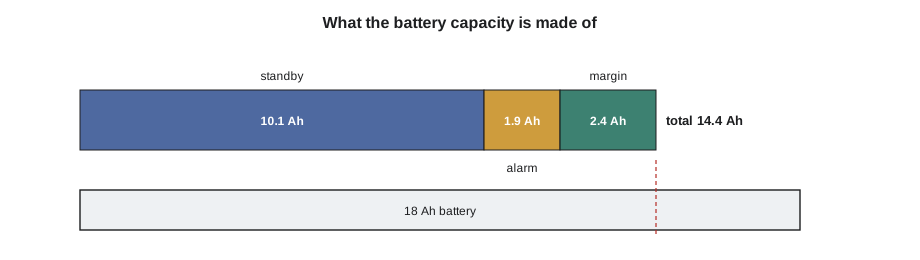
The secondary supply must run the system for a standby period and then the alarm load for an alarm period. Under the NBC, as FAT-130 lesson 7 explains, the usual requirement is 24 hours of supervisory operation followed by 30 minutes of alarm, with 2 hours of alarm for high buildings covered by Subsection 3.2.6 and some other cases; check the code for the building. The battery is sized from the standby current times the standby hours plus the alarm current times the alarm hours, multiplied by a margin for ageing and temperature, commonly 1.2, or the manufacturer's figure if greater. Then the next standard battery size up is chosen.
# Battery calculation for a panel
standby_a = 0.42        # A, total standby current
alarm_a = 3.8          # A, total alarm current
t_standby = 24          # h
t_alarm = 0.5          # h (30 min alarm)
margin = 1.2
sizes = [7, 12, 18, 26, 33, 40, 55]
ah = (standby_a * t_standby + alarm_a * t_alarm) * margin
pick = next(s for s in sizes if s >= ah)
print(f"Standby {standby_a * t_standby:.2f} Ah + alarm {alarm_a * t_alarm:.2f} Ah, x {margin} = {ah:.1f} Ah")
print(f"Choose {pick} Ah batteries")Standby 10.08 Ah + alarm 1.90 Ah, x 1.2 = 14.4 Ah Choose 18 Ah batteries
Worked problem
Spotting the error in a battery calculation
Nadia's calculation for a high building shows 24 h standby at 0.42 A and 30 min alarm at 3.8 A, a margin of 1.2 and a result of 14.4 Ah. What is wrong?
Show solution
- The building is a high building under 3.2.6, so the alarm period is 2 hours, not 30 minutes.
- Alarm: 3.8 A × 2 h = 7.6 Ah. Standby: 0.42 A × 24 h = 10.08 Ah.
- Total 17.68 Ah × 1.2 = 21.2 Ah.
- The next standard size is 26 Ah, not 18 Ah.
Answer: The alarm period was wrong; the answer is 26 Ah. On the exam, read the building description for the alarm period.
Power supplies and loading
Each power supply output has a rating, and the designer checks that the alarm load on each output, and on the supply as a whole, stays within it, usually with some spare capacity (FAT-130 lesson 6). The primary supply comes from a dedicated branch circuit, locked and labelled, and the panel must report loss of primary power. Remote power supplies, or booster supplies, add notification capacity far from the panel and must carry their own batteries and follow the panel's synchronization (FAT-210 lesson 11).
Practice set: calculations
Gerry's rule for calculation questions is to write the setup line before touching the calculator: every input, with its unit and where it came from. Most wrong answers on calculation questions come from the setup, not the arithmetic. He gives five problems and checks only the setup lines first.
Problem 1. A 16 AWG notification circuit runs 90 m one way to six horn-strobes drawing 0.18 A each at the maximum listed current. What is the voltage at the last appliance by the lumped method? Setup: start voltage 20.4 V; current 6 × 0.18 = 1.08 A; loop length 2 × 90 = 180 m; resistance 13.2 Ω per km, so 2.38 Ω. Drop 1.08 × 2.38 = 2.57 V. End voltage 17.8 V, which passes the 16 V minimum.
Problem 2. The same circuit is extended to ten appliances on the same wire and length. Does it still pass? Setup: current 10 × 0.18 = 1.8 A, same loop resistance. Drop about 4.3 V, end voltage about 16.1 V. It passes by a tenth of a volt by the lumped method, which is too close for comfort; a point-to-point calculation would show more margin, but the designer might still choose heavier wire.
Problem 3. Two resistors of 10 kΩ are connected in parallel by mistake at an end-of-line location. What resistance does the panel see? Setup: parallel resistance R = (10 × 10) / (10 + 10) = 5 kΩ. If the panel expects 10 kΩ, it may show trouble or it may not, depending on its tolerance; either way, the circuit is wrong. This is the kind of fault practical exams like to set.
Problem 4. A panel draws 0.30 A in standby and 2.5 A in alarm in a building that is not covered by 3.2.6 and needs 30 minutes of alarm. What battery is needed with a 1.2 margin? Setup: standby 0.30 × 24 = 7.2 Ah; alarm 2.5 × 0.5 = 1.25 Ah; total 8.45 × 1.2 = 10.1 Ah. Next size: 12 Ah.
Problem 5. A strobe is listed at 0.12 A at 24 V and 0.16 A at 16 V. Which current goes in the voltage-drop calculation? Answer: the maximum listed current over the regulated range, 0.16 A, because strobes draw more current as voltage falls. Using 0.12 A would understate the drop on exactly the circuits most at risk.
Formula sheet
| Quantity | Formula | Remember |
|---|---|---|
| Ohm's law | V = I R | Use ohms, amps and volts |
| Power | P = V I | Watts |
| Series resistance | R = R1 + R2 + ... | Current is the same everywhere |
| Parallel resistance (two) | R = R1 R2 / (R1 + R2) | Voltage is the same across each branch |
| Loop resistance | 2 × length × resistance per length | Double the one-way length |
| Voltage drop | I × loop resistance | Start at 20.4 V; use maximum listed current |
| Battery | (Is ts + Ia ta) × margin | Alarm period from the NBC |
On exam day, Sasha writes this sheet from memory on her scratch paper in the first minute, if scratch paper is allowed. It costs a minute and saves several later.
Checking a calculation
On a timed exam, there is rarely time to work a calculation twice, but there is always time to check that the answer makes sense. Gerry's three checks take a few seconds each. First, the units: an answer in amps when the question asks for ampere-hours means a step was missed. Second, the size: a voltage drop larger than the starting voltage, or a battery of 300 Ah for a small panel, means a decimal point is wrong. Third, the direction: more devices, longer wire or a longer alarm period must make the answer worse, never better. If a choice on the answer list matches a common mistake, such as forgetting to double the wire length, the examiner put it there on purpose.
# The distractors on a voltage-drop question are often common mistakes
i, r_per_m, length, v_start = 1.5, 0.0132, 100, 20.4
right = v_start - i * 2 * length * r_per_m
one_way = v_start - i * length * r_per_m
from_24 = 24 - i * 2 * length * r_per_m
print(f"Correct (loop length, 20.4 V start): {right:.1f} V")
print(f"Forgot to double the length:         {one_way:.1f} V")
print(f"Started at 24 V: {from_24:.1f} V")Correct (loop length, 20.4 V start): 16.4 V Forgot to double the length: 18.4 V Started at 24 V: 20.0 V
All three numbers would appear on a well-written multiple-choice question. The candidate who knows the setup picks the first one; the candidate who rushes picks whichever their mistake produces.
One last calculation habit: round only at the end. Rounding the current, then the resistance, then the drop can move an answer by a tenth of a volt, enough to change a pass into a fail on a circuit that is close to the limit, and enough to land on a distractor.
Common mistakes
MistakeStarting voltage-drop calculations at 24 V.
InsteadStart at the end-of-discharge voltage, usually 20.4 V.
MistakeUsing nominal appliance current.
InsteadUse the maximum listed current.
MistakeForgetting to double the one-way length.
InsteadLoop resistance uses both conductors.
MistakeUsing the wrong alarm period.
InsteadCheck the NBC for the building: 30 min, 2 h or other.
MistakeChoosing a battery smaller than the calculated capacity.
InsteadChoose the next standard size up.
Summary and key terms
- V = I R and P = V I underpin every calculation.
- Loop resistance uses twice the one-way length.
- The last notification appliance must see at least 16 V at end-of-discharge voltage.
- Battery Ah = standby plus alarm, times the margin; alarm period from the NBC.
- Check every output and supply against its rating.
- End-of-line resistor
- A resistor at the far end of a circuit that lets the panel supervise it.
- Loop resistance
- The resistance of both conductors of a circuit.
- End-of-discharge voltage
- The battery voltage at the end of its required duty, about 20.4 V for a 24 V system.
- Point-to-point method
- A voltage-drop calculation done segment by segment.
- Margin
- A factor added to battery capacity for ageing and temperature.
Practice problems
Work each problem on paper first, then reveal the answer to check.
What current flows through a 4.7 kΩ end-of-line resistor at 24 V?
Show answer
About 5.1 mA.
What is the minimum voltage for a 24 V regulated appliance?
Show answer
16 V.
Which method of voltage drop is more conservative?
Show answer
The lumped-load method.
Why do strobe currents matter most at low voltage?
Show answer
Strobes draw more current as voltage falls.
After calculating 21.2 Ah, which standard battery size is chosen?
Show answer
26 Ah.
Lesson quiz · 5 questions
Score 60% or more to complete this lesson.
Create a free account to save your progress, take quizzes and earn a certificate.