
FAT-210 · Lesson 5 of 12 · 20 min
Initiating circuits and supervision
Cartwright Distribution Centre has more supervisory points than alarm points. Its sprinkler system has four risers, each with a control valve, a waterflow switch and a pressure gauge; the dock has a dry-pipe system with a low-air switch; the fire pump has running, power-failure and phase-reversal signals; and the heated valve rooms have low-temperature switches. Every one of those is a contact device wired to an input module, and every one has to report the right kind of signal at the right time. Gerry walks Sasha down the riser room wall. 'The detectors get all the attention,' he says, 'but in a sprinklered warehouse, these switches are the fire alarm. If the waterflow switch doesn't report, nobody knows the sprinklers are fighting a fire until the smoke reaches the office.' This lesson covers how the panel monitors contact devices, how it supervises their wiring and what it does with each kind of signal.
Initiating device circuits
An initiating device circuit is any circuit that brings a contact or a two-wire detector's signal into the panel without the device having its own address. It may be a conventional zone on the panel itself, or the short circuit between an addressable input module and the switch it watches. FAT-130 covers the electrical side: the supervisory current, the end-of-line resistor and the voltage drop. Here the focus is on what the panel does with the circuit and how it is wired so that every fault is caught.
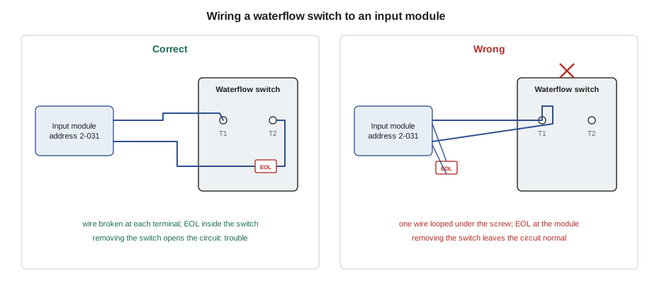
The rule that matters most is that the panel must be able to detect the removal of any device or the breaking of any wire. That is why the wires must be broken at each device terminal, with the incoming wire on one terminal and the outgoing wire on another, or with separate incoming and outgoing conductors under the same terminal where the device is listed for it. Looping one continuous wire under a terminal screw without cutting it means that if the device is removed, the circuit stays complete and the panel never knows. The installation standards in both countries forbid this, and an inspector who finds an unbroken loop will reject the circuit.
The end-of-line device must be at the electrical end of the circuit, after the last device, so the supervisory current passes every connection. Putting the end-of-line resistor at the panel or at the module, as some installers do for convenience, leaves the whole field wiring unsupervised. Where a module is mounted beside the switch it watches, the end-of-line device goes in the switch housing or the box beside it, as the module's manual shows. Some modules have an end-of-line resistor built in for exactly this case, and the manual says so.
What the panel sees
On a supervised contact circuit the panel recognizes four basic states, and the module or zone reports each one. Normal means the supervisory current matches the end-of-line value. Active means a device has closed its contacts, raising the current; the panel reports this as alarm, supervisory or another signal depending on how the point is programmed. Open means the current has dropped to near zero because a wire has broken or a device has been removed; the panel reports a trouble. Short, on some circuits, means the two wires have touched; depending on the circuit and its programming it is reported as a trouble or treated as active. Many panels also measure the circuit's leakage to ground, which the next section covers.
# Decoding an input module circuit from its measured resistance (illustrative bands)
R_EOL = 47000            # end-of-line resistor value (ohms) for this module
bands = [                # (upper limit in ohms, state reported)
    (100, "short"),
    (20000, "active"),
    (80000, "normal"),
    (10 ** 9, "open"),
]
def state(r):
    for limit, name in bands:
        if r < limit:
            return name
readings = {"WF-1 riser 1": 46800, "WF-2 riser 2": 2200, "TS-3 riser 3 valve": 10 ** 8,
            "LA-4 dock low air": 47100, "LT-5 valve room cold": 35}
for point, r in readings.items():
print(f"{point:22s} {r:>11,} ohms -> {state(r)}")WF-1 riser 1 46,800 ohms -> normal WF-2 riser 2 2,200 ohms -> active TS-3 riser 3 valve 100,000,000 ohms -> open LA-4 dock low air 47,100 ohms -> normal LT-5 valve room cold 35 ohms -> short
The output reads like a quick tour of the riser room: riser 2's waterflow switch is active, riser 3's tamper circuit is open and needs fixing, and the valve room low-temperature circuit is shorted. The bands are illustrative; each module's manual gives its own end-of-line value and the ranges it uses.
Ground faults
A ground fault on a fire alarm circuit is a conductor that has made an electrical connection to the building's metal or to earth, through damaged insulation, a wire pinched against a box, or water in a junction box. One ground fault usually doesn't stop the circuit working, but two on different conductors can create a path that looks like a short or an alarm, or that disables a whole section. For that reason panels monitor every field conductor for leakage to ground and report a ground fault trouble when it falls below a threshold. Most panels report one common ground fault for the whole system, or one per power supply, so finding which circuit it is on is a technician's task.
Finding a ground fault starts at the panel. With the building informed and the system watched, the technician disconnects field circuits one at a time, checking after each whether the ground fault trouble clears. When it clears, that circuit holds the fault; the circuit is then halved with a meter set to measure resistance from each conductor to ground. Some panels show the ground fault per loop or per circuit, which saves time. A common cause in warehouses like Cartwright is condensation in junction boxes on outside walls or in unheated areas, and the fix there is a sealed box and a drip loop, not just new wire.
Supervisory signals and how they behave
Supervisory devices watch the sprinkler and suppression systems, and each type behaves a little differently. A valve tamper switch operates when a control valve moves away from fully open, within a small fraction of its travel, so that a valve being closed for maintenance or tampered with is reported long before it is fully shut. A low-air switch on a dry-pipe system operates when the air pressure falls below its setting, warning that the system may trip or freeze. A low-temperature switch in a valve room operates before the water in the pipes can freeze. Fire pump signals report the pump running, a loss of power or a phase reversal. Each is programmed as a supervisory point, not an alarm.
Supervisory signals are latching or non-latching depending on the device and the code. A valve tamper is usually non-latching, so it restores when the valve is reopened, which tells the operator the valve is open again. A low-air or low-temperature signal latches until reset on some systems, so a brief condition isn't missed. A fire pump running signal is a supervisory signal on most systems; in some jurisdictions a pump running is treated as an alarm. The sequence of operation, covered in lesson 9, says which behaviour each point needs, and the panel is programmed to match.
At Cartwright, the sprinkler fitters close valves several times a year for maintenance. The building's procedure, required by the fire code and the inspection standard, is that the fire alarm contractor or the monitoring centre is told first, the closed valve is recorded as an impairment, and the panel's supervisory signal is acknowledged but never disabled. A supervisory point disabled for a valve closure and forgotten is how sprinkler systems end up shut off for months.
Waterflow and the retard delay
A waterflow switch detects water moving in the sprinkler pipe, which normally means a sprinkler head has opened. But water also moves briefly when the city's water pressure surges, a pump starts, or air trapped in the pipe compresses. To avoid false alarms from these surges, most vane-type waterflow switches have a mechanical or electronic retard, a delay that the flow must outlast before the switch closes its contacts. The retard is set on the switch, and the panel should not add a second delay on top of it, because the total delay before the alarm would then be too long.
The standards limit the total time from the start of flow to the alarm signal, commonly to 90 seconds, measured from the moment water starts to flow from the inspector's test connection. During the inspection, the sprinkler fitter opens the test valve and the technician times how long the panel takes to show the alarm. A switch whose retard has been set to its maximum, or a panel input with an added delay, can push the total over the limit. Riser 3 at Cartwright needed its retard reduced from the factory setting after the last test for exactly this reason.
# Waterflow test timing: start of flow to panel alarm (limit 90 s)
LIMIT = 90
tests = [   # (riser, switch retard setting in s, extra delay programmed at the panel in s, measured total in s)
    ("Riser 1", 45, 0, 52),
    ("Riser 2", 60, 0, 71),
    ("Riser 3", 90, 0, 104),
    ("Riser 4", 30, 30, 69),
]
for riser, retard, panel_delay, total in tests:
    issues = []
    if total > LIMIT:
        issues.append(f"over the {LIMIT} s limit")
    if panel_delay:
        issues.append("delay added at the panel; remove it")
print(f"{riser}: retard {retard:3d} s, panel {panel_delay:2d} s, measured {total:3d} s -> {'; '.join(issues) or 'pass'}")Riser 1: retard 45 s, panel 0 s, measured 52 s -> pass Riser 2: retard 60 s, panel 0 s, measured 71 s -> pass Riser 3: retard 90 s, panel 0 s, measured 104 s -> over the 90 s limit Riser 4: retard 30 s, panel 30 s, measured 69 s -> delay added at the panel; remove it
Non-fire inputs and their place
Fire alarm panels often monitor things that aren't fire signals: a kitchen hood suppression system, a clean agent system, a generator running signal, or a door that is supposed to stay closed. These inputs are programmed according to what they are. A kitchen suppression system discharging is normally an alarm input, because it means there is a fire. A generator running is a status signal with no fire response. The panel must keep fire signals ahead of everything else in priority, and the standards limit how non-fire signals may be combined with fire alarm functions so that they can never delay or hide a fire signal.
Worked problem
A ground fault that comes and goes
Every morning around 7:00 the Cartwright panel reports a ground fault trouble, which clears by noon. What is likely happening, and how should Sasha find it?
Show solution
- A ground fault that appears in the cool morning and clears by midday points to moisture: condensation or a wet box.
- It must be found while it is present, so Sasha arranges to be on site early.
- With the monitoring centre informed, she disconnects field circuits one at a time until the trouble clears.
- Once the circuit is found, she halves it with a meter measuring each conductor to ground.
Answer: The fault is on the circuit to the dock dry-pipe valve's low-air switch, in an unsealed junction box on the outside wall of the unheated dock. Condensation forms there each night. Sasha replaces the box with a sealed one, adds a drip loop to the conduit entry, and the trouble doesn't return.
Supervising the power to control devices
Some devices on initiating and control circuits need their own power to work, such as a four-wire smoke detector, a duct detector with its own relay, or a beam detector, and that power must be supervised too. The usual method is an end-of-line power supervision relay at the last powered device: the relay is held energized by the power circuit, and its contact is wired in series with the initiating circuit. If the power fails anywhere along its run, the relay drops out, the initiating circuit opens, and the panel reports a trouble. Without that relay, a lost power feed would leave the devices dead with the panel showing normal.
Common mistakes
MistakeLooping an unbroken wire under a device terminal.
InsteadBreak the wire at each terminal so removing the device causes a trouble.
MistakeMounting the end-of-line resistor at the module.
InsteadPut it after the last device, as the module manual shows.
MistakeDisabling a tamper point during a valve closure.
InsteadAcknowledge the supervisory signal and record the impairment instead.
MistakeAdding a panel delay to a waterflow input that already has a retard.
InsteadKeep the total from flow to alarm within the limit.
MistakeReplacing wet wire without fixing the source of the water.
InsteadSeal the box and correct the conduit entry.
Summary and key terms
- Initiating circuits bring contact and two-wire device signals into the panel or an input module.
- Wires must be broken at each terminal and the end-of-line device must follow the last device.
- The panel recognizes normal, active, open and short states, and reports ground faults separately.
- Supervisory devices report off-normal valves, air pressure, temperature and fire pumps.
- Waterflow switches use a retard to ignore surges, with the total time to alarm limited, commonly to 90 seconds.
- Non-fire inputs are programmed for what they are and never take priority over fire signals.
- Initiating device circuit
- A supervised circuit carrying signals from non-addressable initiating devices.
- Retard
- A delay on a waterflow switch that ignores brief pressure surges.
- Valve tamper switch
- A switch that reports a sprinkler control valve moving off fully open.
- Ground fault
- An unwanted electrical connection between a circuit conductor and the building's metal or earth.
- Non-latching
- Restoring automatically when the condition clears.
- Impairment
- A period when part of a fire protection system is out of service.
Practice problems
Work each problem on paper first, then reveal the answer to check.
A waterflow switch has a 60 s retard and the panel adds 45 s. Is the total acceptable against a 90 s limit?
Show answer
No: 105 s is over the limit; remove the panel delay.
Why must a valve tamper switch operate early in the valve's travel?
Show answer
So a valve being closed is reported long before it is shut.
A module reads near zero ohms on its circuit. What state is that?
Show answer
A short.
What is the first step in finding a system-wide ground fault?
Show answer
Disconnect field circuits one at a time until the trouble clears.
Lesson quiz · 5 questions
Score 60% or more to complete this lesson.
Create a free account to save your progress, take quizzes and earn a certificate.