
FAT-210 · Lesson 11 of 12 · 19 min
Networked panels and remote power supplies
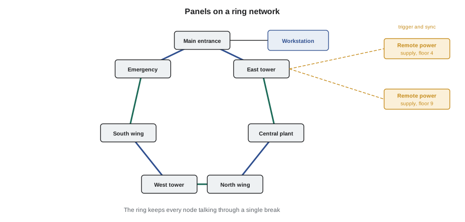
Eastview General Hospital has seven fire alarm panels, one in each wing and one in the central plant, and from the security office they look like one system. An alarm in the east tower shows on every panel's display and on the graphic workstation at security; a nurse acknowledging at a wing annunciator acknowledges everywhere; and a firefighter pressing silence at the main entrance silences the whole hospital. 'If the network goes down,' the facilities manager explains to Sasha, 'each panel still protects its own wing. It just stops telling the others.' This lesson covers how fire alarm panels are networked, what each panel does on its own and what the network adds, and the remote power supplies that carry notification power to the far ends of large buildings.
Why panels are networked
A single panel has limits: a certain number of loops, notification circuits and relays, and a certain distance its circuits can run. Large buildings and campuses outgrow one panel, and they also benefit from having panels close to the devices they serve, so circuits stay short and a problem in one area stays local. Networking lets several panels, each called a node, share information so they act as one system. Every node can see every event, any node's display or a central workstation can show the whole system, and the logic can link an input on one node to outputs on another. The network is listed with the panels, so only the network cards, cable types and node counts the manufacturer lists are used.
Each node still runs its own devices and circuits, and the standards expect it to keep doing so if the network fails. This is called degraded or local mode: a panel cut off from the network still detects alarms on its own loops, sounds its own notification circuits, operates its own control outputs and, where it has its own communicator, still reports off site. What it loses is the global part: other nodes won't see its events, and its outputs won't respond to inputs elsewhere. Good network design puts each fire compartment's inputs and outputs on the same node wherever possible, so that a network failure changes as little as possible.
Network media and classes
Panel networks use either copper pairs, often running a manufacturer's own protocol, or optical fibre, which is immune to electrical noise and can run long distances between buildings. Most fire alarm networks are wired as a ring, so the network keeps working through a single break, which CAN/ULC-S524 treats as a Class A arrangement for links between panels. Where panels are connected through an Ethernet network, the design must show how the network's faults are detected and reported, and the network equipment must be listed or approved for fire alarm use. Each link is supervised, and a break or a lost node produces a trouble on every panel.
The network's cable is chosen and installed as carefully as any loop. Copper network cable is kept away from power and notification wiring; fibre has its own bend radius and connector cleaning rules; and the two directions of a ring are routed apart, as for any Class A circuit. Between buildings, fibre also avoids the ground potential differences that can damage copper circuits.
# What each node can still do when the network ring breaks in two places (illustrative)
ring = ["Main entrance", "East tower", "Central plant", "North wing", "West tower", "South wing", "Emergency"]
breaks = [("East tower", "Central plant"), ("West tower", "South wing")]
links = [(ring[i], ring[(i + 1) % len(ring)]) for i in range(len(ring))]
up = [l for l in links if l not in breaks and (l[1], l[0]) not in breaks]
groups, seen = [], set()
for node in ring:
    if node in seen:
        continue
    group, stack = set(), [node]
    while stack:
        n = stack.pop()
        if n in group:
            continue
        group.add(n)
        stack += [b for a, b in up if a == n] + [a for a, b in up if b == n]
    seen |= group
    groups.append(sorted(group))
print("Ring segments still talking:", len(groups))
for g in groups:
    print("  ", ", ".join(g))
print("Every node keeps local detection, notification and control; only links between segments are lost.")Ring segments still talking: 2 East tower, Emergency, Main entrance, South wing Central plant, North wing, West tower Every node keeps local detection, notification and control; only links between segments are lost.
With one break, a ring loses nothing. With two, it splits into segments that can still talk among themselves but not to each other. The script shows the two segments that two breaks create at Eastview, and reminds the reader of the most important point: every node still protects its own wing.
Global and local programming
On a network, each rule in the logic is either local, using inputs and outputs on one node, or global, linking inputs on one node to outputs on another. Global rules are what make a network act as one system: an alarm anywhere sounding the evacuation signal in a whole building, a duct detector on one node shutting down a fan wired to another, or a firefighter's silence at the main entrance silencing every node. The programming software usually compiles the whole network's program at once and downloads each node's share, and every node checks that the others are running the same program version. A node running an old program is reported as a trouble.
Because global rules depend on the network, the sequence of operations says what happens if they can't run. At Eastview, each wing's panel sounds its own wing in alarm even with the network down, and the security office's procedures say that a network trouble means staff on the phone to each wing until it is fixed. During acceptance testing, the network is deliberately broken to confirm each node behaves as the sequence says.
Network annunciators and workstations
Networks make it easy to put displays where they are needed. A network annunciator is a display node that shows the events of the whole network, or of a selected part, and may offer controls. A graphic workstation, often a computer listed for fire alarm use, shows floor plans of every building, event lists and histories, and lets trained operators acknowledge and control the system. At Eastview, every nursing unit has an annunciator that shows its own wing in detail and the rest of the hospital as a summary, and the security office has a workstation that shows everything. The rules from lesson 10 apply to all of them: labels from one point list, controls that behave the same everywhere, and access levels for each control.
Remote power supplies
Notification appliances draw a lot of current, especially strobes, and a panel's own notification circuits soon run out of capacity and voltage on long runs. Remote power supplies, sometimes called notification circuit extenders or booster power supplies, solve this. Each is a cabinet with its own AC supply, battery charger, standby batteries and several notification circuits, mounted close to the appliances it powers. The panel tells it when to operate, either through one of its own notification circuits wired to the power supply's trigger input or through an addressable control module, and the power supply then drives its own circuits with the temporal pattern and sync signals the system uses.
A remote power supply is part of the fire alarm system and is supervised like one. Its AC power, batteries, charger and output circuits are all monitored, and any fault is sent back to the panel as a trouble, either through a trouble contact wired to a monitor module or by opening the triggering circuit. Its sync must follow the system's sync source, as lesson 6 described, or its strobes will flash out of step with the rest of the building. Its batteries are sized for the same standby and alarm times as the panel's, which FAT-130 covers, and its location, dedicated circuit and breaker are recorded on the drawings so a technician can find them.
# Remote power supply circuit loading and sync source check (illustrative)
supplies = {   # name: (circuit rating A, [(circuit, load A)], sync follows)
    "RPS-4 (floor 4)": (2.5, [("NAC 1", 1.62), ("NAC 2", 1.88), ("NAC 3", 0.94), ("NAC 4", 0.0)], "panel"),
    "RPS-9 (floor 9)": (2.5, [("NAC 1", 2.31), ("NAC 2", 1.45), ("NAC 3", 1.12), ("NAC 4", 0.66)], "panel"),
    "RPS-14 (floor 14)": (2.5, [("NAC 1", 1.74), ("NAC 2", 2.62), ("NAC 3", 0.88), ("NAC 4", 0.0)], "own generator"),
}
for name, (rating, circuits, sync) in supplies.items():
    issues = [f"{c} at {i / rating * 100:.0f} %" for c, i in circuits if i > rating * 0.8]
    if sync != "panel":
        issues.append("sync not linked to the system source")
    total = sum(i for c, i in circuits)
print(f"{name}: {total:4.2f} A total -> {'; '.join(issues) if issues else 'OK'}")RPS-4 (floor 4): 4.44 A total -> OK RPS-9 (floor 9): 5.54 A total -> NAC 1 at 92 % RPS-14 (floor 14): 5.24 A total -> NAC 2 at 105 %; sync not linked to the system source
Of Riverlight's three remote power supplies, two need attention: RPS-9 has one circuit above 80 percent of its rating, and RPS-14 has a circuit over its rating altogether as well as its own sync generator. The over-rated circuit would trip or sag in a real alarm, and the sync error would make floor 14's strobes flash out of step with the rest of the tower.
Planning for the future
Networks and remote power supplies make large systems possible, but they also make them complicated. The design package for a networked system includes a network diagram showing every node, its location and its links; the node address and program version for each; every remote power supply with its circuits, trigger source, sync source and battery size; and the global rules in the sequence of operations. When Riverlight's panel upgrade is complete, the tower will have a main panel, two network nodes in the electrical rooms on floors 7 and 13, and the three remote power supplies, and every one of them will be on the drawings Sasha checks at the final test.
Worked problem
A remote power supply that stayed quiet
During Riverlight's annual test, the horn-strobes on floor 14 don't operate when Sasha activates a detector there, although every other floor sounds. The panel shows no trouble. What should she check?
Show solution
- Floor 14's appliances are on RPS-14, so the power supply or its trigger is the likely problem.
- No trouble at the panel suggests the power supply hasn't reported a fault, or its trouble contact isn't supervised.
- If the trigger circuit from the panel isn't connected, the power supply would never be told to operate.
- She checks the trigger input, the power supply's own status lights, and the wiring of its trouble contact back to the panel.
Answer: The trigger circuit had been disconnected during a renovation and the end-of-line resistor moved to the power supply's terminals, so the panel saw a healthy circuit. The power supply's trouble contact was also unwired. Sasha restores the trigger wiring with the end-of-line device in the right place, connects the trouble contact to its monitor module, links the sync, and retests floor 14 with a stopwatch on the strobes.
Testing a network
Network tests are part of the acceptance test and the annual inspection. Each link in the ring is opened in turn to confirm the network carries on and every node reports the trouble. A node is powered down to confirm the others report it missing and that its own area still works in local mode. A global rule is tested from each end, such as an alarm on one node sounding the notification circuits on another. And the network annunciators and the workstation are checked to confirm they show events from every node. The results are recorded per node and per link, with the program version of each node.
Network tests are repeated after any program download, because a download changes every node at once. Gerry's habit is to test one global rule from each node after every download, even a small one, before the job is signed off.
Common mistakes
MistakePutting a fire compartment's inputs and outputs on different nodes without need.
InsteadKeep each area's devices and outputs on one node where possible.
MistakeRunning both directions of a network ring in the same raceway.
InsteadRoute the two paths apart.
MistakeLeaving a remote power supply's trouble contact unwired.
InsteadSupervise every power supply back to the panel.
MistakeLetting a remote power supply generate its own sync.
InsteadLink it to the system's sync source.
MistakeLoading a node with a different program version from the others.
InsteadDownload the whole network's program together.
Summary and key terms
- Networked panels act as one system, but each node keeps protecting its own area if the network fails.
- Rings of copper or fibre keep the network working through one break, as a Class A arrangement.
- Global rules link nodes; local rules keep working in degraded mode.
- Network annunciators and workstations show the whole system from any location.
- Remote power supplies extend notification capacity and are supervised, synchronized and battery-backed.
- Network diagrams, node versions and power supply details are part of the record documents.
- Node
- One panel or display on a fire alarm network.
- Degraded mode
- A node working on its own when it has lost the network.
- Global rule
- Logic that links inputs on one node to outputs on another.
- Remote power supply
- A supervised cabinet that powers notification circuits away from the panel.
- Trigger input
- The input that tells a remote power supply to operate its circuits.
- Graphic workstation
- A listed computer that shows and controls a networked fire alarm system.
Practice problems
Work each problem on paper first, then reveal the answer to check.
A network ring has one break. What is lost?
Show answer
Nothing; the ring carries on around the break and reports a trouble.
What does a node do in degraded mode?
Show answer
It keeps local detection, notification and control, but loses global functions.
Why must a remote power supply's trouble contact be wired to the panel?
Show answer
Otherwise its faults are never reported.
A power supply circuit carries 2.62 A on a 2.5 A rating. What happens in a real alarm?
Show answer
It can trip or sag; split the circuit.
Lesson quiz · 5 questions
Score 60% or more to complete this lesson.
Create a free account to save your progress, take quizzes and earn a certificate.