
FAT-210 · Lesson 3 of 12 · 19 min
Addressable systems and their loops
Tamarind House has an addressable panel with two loops, installed when the building was converted to offices. On a quiet Tuesday Sasha spends the morning at its keypad with Gerry, scrolling through every address: smoke detector 1-001, fourth-floor elevator lobby; heat detector 1-014, fourth-floor electrical room; input module 2-031, fourth-floor waterflow; control module 2-060, AHU-2 shutdown. 'On a conventional panel the building is twelve zones,' Gerry says. 'Here it is three hundred and forty separate things, and the panel knows every one of them by name. That is the power of addressable, and it is also why the programming has to be right.' This lesson explains how addressable loops work, how devices are addressed and polled, how much a loop can carry, and how isolators keep one wiring fault from taking out half a building.
Polling and addresses
In an addressable system the panel talks to devices over a two-wire loop that Canadian standards call a data communication link and most manufacturers call a signalling line circuit or SLC. The same two wires carry power to the devices and the data between them and the panel. The panel polls each address in turn, sending a short message, and the device at that address replies with its type and status. A full poll of a loop of a few hundred devices takes a few seconds; when a device reports an alarm, most panels interrupt the normal poll and respond at once. Because every device answers individually, the panel knows within seconds when a device is missing, has the wrong type, or has two devices sharing one address.
Addresses are set in one of three ways, depending on the manufacturer. Some devices have rotary dials or switches on the base or the head, set by the installer before the device goes up. Some are set with a handheld programmer that writes the address into the device's memory. Others are addressed automatically by the panel, which discovers every device on the loop and numbers them in wiring order or by serial number. Whichever method is used, the address plan is drawn up before installation, so that the address on the drawing, the label on the device and the description in the panel all match. A device installed with the wrong address may work perfectly and report the wrong room.
| Field | Example | Why it matters |
|---|---|---|
| Loop and address | 1-014 | How the panel finds the device |
| Device type | Heat, fixed temperature | Sets alarm behaviour and test method |
| Location text | Floor 4 electrical room 412 | What responders read on the display |
| Zone or group | Floor 4 | Links the device to outputs and annunciation |
| Special options | None (no verification on heat) | Verification, sensitivity, day and night modes |
Analog detectors and what the panel learns
Most addressable smoke detectors are analog: instead of deciding alarm themselves, they send the panel a value representing how much smoke or heat they sense. The panel compares the value with an alarm threshold set in the program, and can also apply a lower pre-alarm threshold that alerts staff before a full alarm. Because the panel sees every reading, it can track each detector's clean-air value as dust builds up and adjust for it, which manufacturers call drift compensation. When the compensation reaches its limit, the panel reports a maintenance or dirty-detector trouble so the detector can be cleaned or replaced before it causes a nuisance alarm.
Analog values are also a diagnostic tool. A detector whose value creeps upward every afternoon may be near a kitchen or a dusty air supply; a heat detector that reads unusually warm may be close to a light or a heater. Many panels can print a report of every detector's current value and its percentage of the alarm threshold, and a technician reading that report can find problems before the building's occupants notice them. At Tamarind House, Sasha's report shows two detectors on the fourth floor reading much higher than the rest, both above the new suspended ceiling that the fit-out added, which explains a pair of nuisance alarms in the spring.
How much a loop can carry
Every loop has limits set by the panel and the devices: the number of addresses, the total current the devices draw, and the length and electrical properties of the wire. A typical modern loop card supports a few hundred addresses, often split between detectors and modules, and each manufacturer publishes a maximum loop length for each wire size, usually in the range of a few thousand metres for common fire alarm cable. The limit comes from the wire's resistance, which drops the voltage the devices see, and its capacitance, which distorts the data. A loop that is too long or uses the wrong cable may work on a quiet day and drop devices when every one of them is trying to report.
The loop's current includes every device's standby current plus the extra current of devices with LEDs lit, isolators and any loop-powered sounder bases. When many devices go into alarm together and light their LEDs, the current rises; panels usually limit how many LEDs they light at once for this reason. Loop-powered sounder bases and relays draw much more and are counted carefully in the loop calculation. The loop calculation is part of the design package, and a technician adding devices to an existing loop should check that it still holds.
# Addressable loop capacity check (illustrative limits; use the panel's manual)
MAX_DET, MAX_MOD = 159, 159            # address limits per loop
I_LOOP = 0.400                         # loop current limit (A)
det_ma, mod_ma, iso_ma, base_ma = 0.30, 0.40, 0.45, 2.5   # standby current per device type (mA)
loops = {
    "Loop 1": {"detectors": 142, "modules": 38, "isolators": 9, "sounder bases": 0},
    "Loop 2": {"detectors": 96, "modules": 61, "isolators": 8, "sounder bases": 24},
}
for name, d in loops.items():
    ma = (d["detectors"] * det_ma + d["modules"] * mod_ma +
          d["isolators"] * iso_ma + d["sounder bases"] * base_ma)
    ok = d["detectors"] <= MAX_DET and d["modules"] <= MAX_MOD and ma / 1000 <= I_LOOP
    spare = MAX_DET - d["detectors"], MAX_MOD - d["modules"]
    print(f"{name}: {d['detectors']} detectors, {d['modules']} modules, {ma:6.1f} mA standby "
f"({ma / 10 / I_LOOP:4.1f} % of limit), spare addresses {spare[0]} / {spare[1]} -> {'OK' if ok else 'OVER'}")Loop 1: 142 detectors, 38 modules, 61.9 mA standby (15.5 % of limit), spare addresses 17 / 121 -> OK Loop 2: 96 detectors, 61 modules, 116.8 mA standby (29.2 % of limit), spare addresses 63 / 98 -> OK
Both loops pass, but loop 1 has only 17 spare detector addresses. A designer planning another fit-out on the floors that loop 1 serves would look at moving some devices to loop 2, or adding a loop card, rather than filling loop 1 to its last address.
Wiring an addressable loop
Addressable loops can be wired in two ways. In the simpler arrangement, the loop leaves the panel and runs out to the devices like a tree, with branches called T-taps where the wire splits. The panel supervises the wiring by polling, so a broken wire shows up as missing devices beyond the break. In the more robust arrangement, the loop leaves the panel on one pair of terminals and returns on another, so the panel can talk to every device from both ends. A single break then loses no devices: the panel reports a trouble and carries on talking around the break. Lesson 4 covers these arrangements as circuit classes. T-taps are allowed only on the simpler arrangement, because a branch can't return to the panel.
The cable itself is chosen for the loop: usually twisted, sometimes shielded, of the size the manufacturer's length table needs, and with the fire rating the building code requires for its location. Running the loop in the same cable or raceway as power circuits or notification circuits is avoided, because induced noise can corrupt the data. Every splice is made in an accessible box with listed connectors, and the loop's polarity is kept consistent, because many devices and isolators care which wire is which.
Isolators: keeping one short from taking out everything
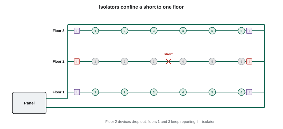
A short circuit across a loop is the most damaging single fault, because it collapses the voltage for every device on that loop. An isolator is a device that watches the loop voltage and opens its section of the loop if it sees a short, so the short is confined to the section between two isolators. The devices outside that section keep working, and the panel reports the devices inside it as missing. Isolators are built into some detector bases and modules, or installed as separate isolator modules, and they are placed so that each protected section matches an area the fire response can afford to lose briefly, such as one floor or one zone.
CAN/ULC-S524 requires isolation on data communication links so that a single short cannot disable the devices of more than a limited part of the system, in practice by floor and by zone, and it sets further rules for links that leave a fire compartment or serve more than one floor. Designers usually place an isolator where the loop enters and leaves each floor, so a short on one floor can never affect another. The exact limits are in the edition of the standard in force, and the panel manual adds its own limit on how many devices may sit between two isolators.
# Isolator check: devices lost if a short occurs in each section (illustrative)
MAX_BETWEEN = 25        # panel manual: maximum devices between isolators
sections = [            # (section, floor or zone it serves, devices in it)
    ("Panel to ISO-1", "Floor 1", 18), ("ISO-1 to ISO-2", "Floor 2", 31),
    ("ISO-2 to ISO-3", "Floor 3", 22), ("ISO-3 to ISO-4", "Floor 3 and 4", 20),
    ("ISO-4 to panel", "Floor 4", 19),
]
for name, area, n in sections:
    notes = []
    if n > MAX_BETWEEN:
        notes.append(f"over {MAX_BETWEEN} devices")
    if " and " in area:
        notes.append("serves more than one floor")
print(f"{name:15s} {area:14s} {n:3d} devices {'; '.join(notes) if notes else 'OK'}")Panel to ISO-1 Floor 1 18 devices OK ISO-1 to ISO-2 Floor 2 31 devices over 25 devices ISO-2 to ISO-3 Floor 3 22 devices OK ISO-3 to ISO-4 Floor 3 and 4 20 devices serves more than one floor ISO-4 to panel Floor 4 19 devices OK
The script flags two sections: one with too many devices between isolators, and one where a single short would take out devices on two floors. Both are fixed the same way, by adding isolators so each floor and each part of a floor stands alone.
Device types and modules
Besides detectors, an addressable loop carries modules that connect everything else. Input or monitor modules watch the contacts of conventional devices such as waterflow switches, tamper switches, kitchen hood suppression systems and pull stations that aren't addressable themselves. Control or relay modules give the panel dry contacts to operate fans, dampers, door holders and elevator recall. Some modules supervise a conventional zone of two-wire detectors, and some drive a small notification circuit. Each module is programmed with a type that tells the panel how to treat its signal: alarm, supervisory, trouble or a non-fire monitoring point.
Programming the wrong type is a classic error. A tamper switch module programmed as an alarm type will evacuate a building every time a sprinkler fitter closes a valve. A waterflow module programmed as a supervisory type will never sound the building. The acceptance test catches these, but only if every module is actually operated during the test, which lesson 12 covers.
Worked problem
A loop that drops devices
After the fourth-floor fit-out at Tamarind House, the panel reports 'DEVICE MISSING' for twelve addresses on loop 1, all on the fourth floor, roughly once a day for a few seconds each time. What should Sasha look at?
Show solution
- Twelve devices on one floor dropping together points to the wiring of that floor, not to the devices.
- Intermittent drops suggest a poor connection or noise rather than a clean break.
- The fit-out added new ceilings and lighting, so a splice may have been disturbed or the loop rerouted near power wiring.
- Checking the loop's resistance and the splices on floor 4, and looking for loop cable bundled with lighting circuits, is the place to start.
Answer: Sasha finds a new run of the loop tie-wrapped to a lighting circuit above the corridor ceiling, with a loose push-in splice. She rewires the splice with listed connectors and has the electrician reroute the loop away from the lighting. The drops stop, and the panel's history over the next week stays clean.
Common mistakes
MistakeInstalling devices before the address plan is final.
InsteadSet addresses from an approved plan so drawings, labels and the panel match.
MistakeAdding devices to a loop without checking the loop calculation.
InsteadCheck addresses, current and length against the panel manual.
MistakeUsing T-taps on a loop meant to return to the panel.
InsteadBranches are only allowed on the simpler wiring arrangement.
MistakeLeaving a loop section that serves two floors without isolation.
InsteadIsolate each floor so one short can't affect another.
MistakeProgramming a module with the wrong signal type.
InsteadCheck every module's type against the sequence of operations.
Summary and key terms
- The panel polls every address on a data communication link (signalling line circuit) and each device replies with its status.
- Addresses come from an approved plan so the drawing, the label and the panel description match.
- Analog detectors send values; the panel applies thresholds, drift compensation and maintenance alerts.
- Loop limits cover addresses, current, length and cable type.
- Isolators confine a short to one section; CAN/ULC-S524 limits how much of the system one fault can disable.
- Modules connect contact devices and control functions, and each must have the right signal type.
- Addressable loop
- A two-wire circuit that carries power and data between the panel and addressable devices.
- Polling
- The panel asking each address in turn for its status.
- Analog detector
- A detector that sends its sensor value to the panel, which decides on alarm.
- Drift compensation
- The panel's adjustment for a detector's slowly rising clean-air value.
- Isolator
- A device that opens its section of a loop when it detects a short circuit.
- T-tap
- A branch in loop wiring, allowed only where the loop does not return to the panel.
Practice problems
Work each problem on paper first, then reveal the answer to check.
A loop has 142 detectors and a 159-detector limit. How many detector addresses are spare?
Show answer
17.
Why do panels limit how many detector LEDs they light at once?
Show answer
Every lit LED adds current to the loop.
Where are isolators usually placed?
Show answer
Where the loop enters and leaves each floor, and between zones.
What happens if a tamper switch module is programmed as an alarm type?
Show answer
Closing a valve would evacuate the building.
Lesson quiz · 5 questions
Score 60% or more to complete this lesson.
Create a free account to save your progress, take quizzes and earn a certificate.