
DCT-350 · Lesson 7 of 12 · 23 min
Cabling and networking review
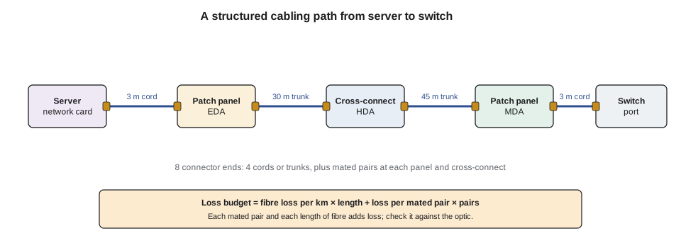
Cabling and networking questions reward technicians who can picture the physical path of a signal: from a server's network card, through a cord, a patch panel, a trunk, a cross-connect and another trunk, to a switch port. This review follows that path through DCT-210, DCT-320 and LVT-210. It covers the TIA-942 spaces, copper and fibre media, MPO and polarity, loss budgets and testing, the basics of switching and addressing a technician needs, and optics. Network configuration is not a technician task at Stonebridge, and it is lightly tested on facility exams, so the focus here is the physical layer and the evidence a technician gathers.
Spaces and topology
TIA-942 names the spaces cabling runs between (DCT-210 lesson 2). The entrance room (ER) is where carriers' cables enter the building; Stonebridge has two, north and south, on separate routes. The main distribution area (MDA) holds the core switches and main cross-connect. Horizontal distribution areas (HDAs) serve rows or groups of rows. A zone distribution area (ZDA) is an optional consolidation point near the racks. The equipment distribution area (EDA) is the rack itself. A meet-me room is where customers and carriers cross-connect to each other, usually in or next to the ER (DCT-210 lesson 9).
Network topology has moved from three-tier (core, aggregation, access) to spine-leaf, where every leaf switch connects to every spine switch and any two servers are the same number of hops apart. AI clusters add rail-optimized fabrics, in which the first GPU in every server connects to the same leaf, the second to another, and so on, to keep collective traffic short (DCT-210 lesson 3, DCT-320 lesson 6).
Copper and fibre media
| Medium | Typical use | Reach to remember |
|---|---|---|
| Direct attach copper (DAC) | Server to top-of-rack switch | About 2 to 3 m at the highest speeds |
| Active electrical cable (AEC) | Within a rack or to the next rack | About 5 to 7 m |
| Category 6A | Management, 10GBASE-T, PoE | 100 m channel |
| OM4 multimode fibre | Short reach within a hall | About 100 m at 100G per lane (SR) |
| OM5 multimode fibre | Short reach, wavelength multiplexing | Similar to OM4 for SR optics |
| OS2 singlemode fibre | Longer runs, between halls and buildings | 500 m (DR) to 10 km (LR) and beyond |
Colour codes help on the floor and appear on exams: OM3 and OM4 multimode jackets are usually aqua (OM4 sometimes violet or heather), OM5 lime green, and OS2 singlemode yellow. Connector colours tell polish: blue for UPC, green for APC with its 8-degree angled end face (LVT-210 lesson 6). Never mate APC with UPC; the angled face against a flat one leaves an air gap and high loss.
MPO and polarity
High-density links use MPO connectors with 8, 12, 16 or 24 fibres in a row. Trunks of MPO cable run between panels, and cassettes or breakout cords turn them into LC connections or feed parallel optics directly (DCT-210 lessons 6 and 7). Polarity is how the system makes sure each transmitter reaches a receiver. TIA-568.3 defines trunk types A, B and C and connectivity methods built from them. Stonebridge uses Method B throughout the campus, with base-12 cassettes in Hall A, base-8 links for 400G-DR4 in Halls B and C, and base-16 MPO-16 APC in Hall D.
The most common exam trap here is mixing methods: a Method A cord on a Method B link, or a flipped trunk, leaves transmitters facing transmitters and the link dark, even though every connector is clean and every loss is low. The DCT-210 capstone found a swapped pair of trunks that tested perfectly and was caught only by checking labels against the port map.
Loss budgets
A loss budget compares the expected loss of a link with the maximum its optic allows. Expected loss is fibre attenuation times length, plus the loss of each mated connector pair, plus each splice. Typical planning values from TIA-568.3 are 0.75 dB per connector pair and 0.3 dB per splice, and about 3.0 dB/km for multimode at 850 nm and 0.4 to 0.5 dB/km for singlemode. Low-loss components are often specified at 0.35 dB or less per pair, which is what makes high-density links with several cassettes fit (LVT-210 lesson 10).
Worked problem
Does the link fit?
A Hall D 400G-SR4 link runs 60 m over OM4 with three mated MPO pairs at 0.35 dB each. The optic's maximum channel insertion loss is about 1.9 dB. Does it fit?
Show solution
- Fibre: 0.060 km × 3.0 dB/km = 0.18 dB.
- Connectors: 3 × 0.35 = 1.05 dB.
- Total: 0.18 + 1.05 = 1.23 dB, against a limit of about 1.9 dB, leaving about 0.67 dB of margin.
Answer: Yes, with about 0.7 dB of margin. With standard 0.75 dB connectors (2.25 dB plus fibre) it would not fit.
# Link loss budget (metres)
def link_loss(length_m, pairs, splices=0, db_km=3.0, pair_db=0.75, splice_db=0.3):
    return length_m / 1000 * db_km + pairs * pair_db + splices * splice_db
cases = [  # name, length m, pairs, pair loss dB, fibre dB/km, optic budget dB
    ("Hall D SR4, low-loss", 60, 3, 0.35, 3.0, 1.9),
    ("Hall D SR4, standard", 60, 3, 0.75, 3.0, 1.9),
    ("Hall B DR4 singlemode", 420, 4, 0.35, 0.5, 3.0),
]
for name, length, pairs, pdb, dbkm, budget in cases:
    loss = link_loss(length, pairs, db_km=dbkm, pair_db=pdb)
    verdict = "fits" if loss <= budget else "too high"
print(f"{name:<24} {loss:4.2f} dB of {budget:3.1f} dB -> {verdict} (margin {budget - loss:+.2f})")Hall D SR4, low-loss 1.23 dB of 1.9 dB -> fits (margin +0.67) Hall D SR4, standard 2.43 dB of 1.9 dB -> too high (margin -0.53) Hall B DR4 singlemode 1.61 dB of 3.0 dB -> fits (margin +1.39)
Cleaning, inspection and testing
Dirty connectors are the most common cause of fibre faults. The rule from LVT-210 and DCT-210 is inspect, clean if needed, inspect again, and only then connect, every time, including new cords straight from the bag. Tier 1 testing measures total loss with a light source and power meter against the budget; Tier 2 adds an OTDR trace that shows where along the link the loss happens. Copper links are certified with a field tester against the category limits. Every result is saved with the link's label so that later faults can be compared with the as-built record (DCT-210 lesson 11).
Switching and addressing at technician level
Technicians do not configure switches at Stonebridge, but they need the vocabulary to read tickets and report evidence (DCT-320 lessons 3 to 6).
- A switch learns which MAC address is on which port and forwards frames only where they need to go.
- VLANs split one switch into separate networks; a trunk port carries several VLANs between switches, tagged so each frame's VLAN is known.
- Link aggregation (LACP) bundles several physical links into one logical link; if one member fails, traffic continues on the others.
- IP addresses identify devices across networks. Point-to-point links between switches often use /31 subnets in IPv4, which hold exactly two addresses.
- Spine-leaf fabrics usually route between switches with BGP and spread traffic over several equal paths (ECMP).
Optics
Optical transceivers come in form factors such as SFP, QSFP and the larger QSFP-DD and OSFP used at 400G and 800G. The name tells the reach and medium: SR for short reach over multimode, DR for 500 m singlemode parallel, FR for 2 km and LR for 10 km duplex singlemode. Digital diagnostics (DDM) report transmit and receive power, temperature and voltage, and the switch raises alarms when a reading crosses a threshold. A receive power that is low only in one direction, on one lane, points to the fibre or connector in that direction, as in the DCT-320 capstone, where an unlatched MPO cord was tilted every time a cabinet door closed (DCT-320 lessons 7, 8 and 11).
Handling rules from DCT-320 lesson 8: wear an ESD strap, keep dust caps on until the moment of connection, never look into an optic or fibre end, and never hot-swap an optic without checking that the port is the one in the ticket and that the customer has agreed.
Exam traps on cabling and networking
- Clean connectors can still give a dark link if polarity is wrong.
- APC (green) and UPC (blue) must not be mated.
- A link that passes Tier 1 loss can still have a bad splice or bend, visible only on an OTDR trace.
- A channel limit includes the cords; a permanent link test does not.
- Receive power is what the far end gets; transmit power is what the local end sends. A fault shows as low receive power at the far end.
- Technicians gather evidence (lights, counters, DDM readings, labels) and escalate; configuration changes are the network team's job under change control.
Physical rules for cable
Many cabling questions test simple physical rules. Copper and fibre both have a minimum bend radius: a common rule for balanced twisted-pair cable is four times the cable diameter, and for fibre cable ten times the diameter when it is not under tension and twenty times while it is being pulled, unless the maker gives other values. Bend-insensitive fibre tolerates tighter bends, but the rule of following the maker's data still applies. Cable ties pulled tight crush cable and change its performance, which is why hook-and-loop straps are used in most data halls. Pathways should not be overfilled; TIA guidance and maker data limit tray fill so that cables at the bottom are not crushed and heat can escape from power-carrying bundles.
Colour helps on the floor. Multimode OM3 and OM4 jackets are usually aqua, though some OM4 is violet; OM5 is lime green; singlemode OS2 is yellow. Connector colours show end-face polish: blue for UPC and green for APC. An APC connector must never be mated with a UPC one, because the angled and flat faces leave a gap that causes high loss and can damage both faces. An exam that shows a green connector going into a blue adapter is asking you to spot exactly that.
Labelling and records
TIA-606 sets out how to label and record cabling infrastructure: each space, rack, panel, port, cable and pathway gets a unique identifier, and labels at both ends of each cable match the records. Stonebridge's port maps in DCIM follow the same scheme (DCT-330 lesson 5). Labels should be machine-printed, durable and readable without moving cables. When a label and the records disagree, the technician stops and resolves the difference before moving anything; the DCT-210 capstone showed how swapped trunks can pass every test and still be wrong.
Power over Ethernet
Power over Ethernet carries power and data on the same copper cable. IEEE 802.3bt Type 4 can deliver up to 90 W at the switch, with about 71 W available at the device after losses. In a data centre, PoE powers cameras, access control readers, wireless access points and some sensors. Bundles of PoE cables run warmer than data-only bundles, which is one reason for limits on bundle size and a reason Category 6A is preferred for PoE runs.
Troubleshooting a dark link
Worked problem
A new 100G link will not come up
A customer reports that a new 100G-SR4 link between a server in Hall A and a switch in the MDA shows no light. The ports are configured. What order of checks gives the fastest answer?
Show solution
- Check the optics: both ends show the right type (SR4 at both ends), seated, and reporting through DDM.
- Read DDM receive power at each end. No light at one end narrows the fault to one direction.
- Check labels and the port map along the path: right panel, right port, right trunk.
- Inspect and clean every connector end face along the path, including the optic ports.
- Check polarity: a Method B link needs the right cords at each end; a wrong cord leaves transmit facing transmit.
- Test the link with a light source and power meter, or an OTDR, against the loss budget.
Answer: Work from simple and likely to complex: optics and DDM, labels, cleanliness, polarity, then test. Most dark links are dirty connectors, wrong ports or polarity errors, not broken fibre.
DDM (digital diagnostic monitoring) readings are useful evidence. Each optic reports its transmit and receive power in dBm against thresholds for warning and alarm. A receive power far below the transmit power at the other end, by more than the loss budget, points to dirt, a bad connector or a damaged cord; no receive power at all points to a wrong port, a polarity error or a break.
Addressing basics
Facility exams test only a little networking, but a few ideas recur. Every network interface has a MAC address burned in by the maker; switches learn which MAC addresses sit behind which ports and forward frames accordingly. IP addresses are assigned by administrators or by DHCP, and the subnet mask or prefix length shows how many addresses share the same network. A /24 network has 256 addresses, of which 254 can be used by hosts; a /26 has 64, with 62 usable. A technician who is asked to confirm a server's management address against a ticket needs to read these numbers correctly, and nothing more.
Exams also like the difference between a cross-connect and an interconnect. A cross-connect joins two panels with a patch cord, so that changes are made by moving cords between panels and the equipment cabling is never disturbed. An interconnect plugs the cord straight from a panel into the equipment port. Cross-connects take more space but make moves safer, which is why Stonebridge uses them in the MDA and HDAs.
More exam traps on cabling
- APC and UPC connectors never mate with each other.
- A link that tests within the loss budget can still be dark because of polarity or the wrong port.
- Category ratings apply to the whole channel: one lower-rated cord limits the whole link.
- Cable ties pulled tight are a fault, not good dressing.
Common mistakes
MistakeConnecting a new cord without inspecting it because it came sealed.
InsteadInspect and clean every connector, new or old, before mating.
MistakeUsing standard 0.75 dB connector values for a high-density AI link and concluding it cannot work.
InsteadUse the specified low-loss values; check the design's component specification.
MistakeSwapping a transceiver as the first step for a flapping link.
InsteadRead DDM both ends, check counters, inspect and reseat cords, then escalate with evidence.
MistakeReversing an MPO trunk to fix polarity on one link.
InsteadUse the site's polarity method consistently; a one-off fix creates the next fault.
Summary and key terms
- TIA-942 spaces are ER, MDA, HDA, ZDA and EDA; meet-me rooms connect customers and carriers.
- DAC and AEC cover short copper runs; OM4 and OM5 short multimode runs; OS2 singlemode longer runs.
- MPO links need a consistent polarity method; Stonebridge uses Method B.
- Loss budget = fibre attenuation × length + connector pairs + splices, compared with the optic's limit.
- Technicians read MAC tables, VLANs, LACP and DDM as evidence; they do not configure the network.
- MDA
- Main distribution area, the space holding the core network and main cross-connect.
- Polarity
- The arrangement that connects each transmitter to the matching receiver.
- Loss budget
- The comparison of a link's expected loss with the maximum its equipment allows.
- APC
- Angled physical contact connector polish, usually green, with an 8-degree end face.
- DDM
- Digital diagnostic monitoring: an optic's readings of power, temperature and voltage.
- Spine-leaf
- A network design in which every leaf switch connects to every spine switch.
Practice problems
Work each problem on paper first, then reveal the answer to check.
What is the expected loss of a 300 m singlemode link at 0.5 dB/km with two connector pairs at 0.5 dB and one splice at 0.3 dB?
Show answer
0.15 + 1.0 + 0.3 = 1.45 dB.
Which jacket colour usually marks OS2 singlemode fibre?
Show answer
Yellow.
How many usable host addresses does an IPv4 /31 point-to-point link have?
Show answer
Two, one at each end.
A link is dark but both ends show transmit power and all connectors are clean. What should you check?
Show answer
Polarity: trunk type, cassette and cord method, and labels against the port map.
Lesson quiz · 5 questions
Score 60% or more to complete this lesson.
Create a free account to save your progress, take quizzes and earn a certificate.