
DCT-350 · Lesson 3 of 12 · 22 min
Facilities review: power
Power is the largest single topic on most facility exams and the one Jamal rated weakest. It is also the topic where exam writers set the most traps, because many terms sound alike: kW and kVA, static and maintenance bypass, N+1 and 2N, transfer and retransfer. This review walks through the power chain the way DCT-220 did, with the numbers and definitions you need to recall quickly, worked examples of the calculations exams ask for, and the traps that catch candidates who half-remember.
The power chain in one paragraph
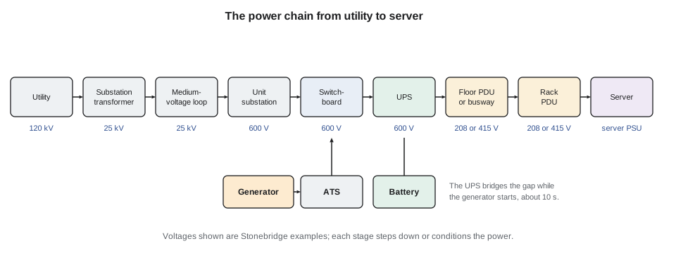
Utility power arrives at high voltage (120 kV at Stonebridge) and is stepped down at the campus substation to medium voltage (25 kV), distributed around the campus, and stepped down again at unit substations to low voltage (600 V). Switchboards feed the UPS systems, which feed floor PDUs that transform to 208Y/120 V in Hall A, or busways at 415 V in Hall D. Branch circuits then feed rack PDUs, and rack PDUs feed the server power supplies. Generators back up the utility through automatic transfer switches, and the UPS bridges the gap while the generators start (DCT-220 lesson 1).
Power, current and voltage
Real power (kW) is what does the work and becomes heat. Apparent power (kVA) is voltage times current, and it is what wires, breakers and transformers must carry. The ratio is the power factor: kW = kVA × PF. Modern server supplies have power factors close to 1, often 0.95 to 0.99, so kW and kVA are close, but UPS and generator ratings are often given in both, and an exam may give you one and ask for the other.
For a three-phase circuit, power is √3 × line-to-line voltage × current × power factor. For a single-phase circuit, it is voltage × current × power factor. The √3 (about 1.732) appears only in three-phase calculations, and forgetting it, or using it on a single-phase circuit, is the most common arithmetic trap on power questions.
Worked problem
Three-phase power and current
A floor PDU in Hall A carries 180 kW of IT load at a power factor of 0.95 on its 600 V input. What current does it draw on each phase, and what does it draw on the 208 V output side?
Show solution
- Input: I = P / (√3 × V × PF) = 180,000 / (1.732 × 600 × 0.95) = 180,000 / 987 = 182 A.
- Output: I = 180,000 / (1.732 × 208 × 0.95) = 180,000 / 342 = 526 A.
- The same power at a lower voltage needs more current, which is why low-voltage feeders and busways are so large.
Answer: About 182 A per phase at 600 V in, and 526 A per phase at 208 V out.
Planning limits: 80 percent and 40 percent
Two planning rules from DCT-130 and DCT-220 appear in exam questions in many forms. First, continuous loads are planned at no more than 80 percent of a breaker's rating, the rule in the Canadian Electrical Code for continuous loads on standard breakers. A 30 A branch circuit is planned for 24 A. Second, in a 2N design where every rack has an A feed and a B feed, each side is planned at no more than 40 percent of its rating in normal running, so that if one side fails the other can carry the whole load at 80 percent. A rack PDU strip rated 24 A for continuous use should therefore show no more than about 9.6 A on each side during normal operation, not 24.
This is the single most tested idea in data centre power: redundancy is only real if the surviving path can carry the whole load. A rack drawing 15 A on each of its two feeds looks fine on each meter, but if one feed is lost the other must carry 30 A, which trips a 30 A breaker under a continuous load (DCT-220 lesson 3, the A-17-04 trip).
UPS systems
A double-conversion UPS rectifies incoming AC to DC, keeps the battery charged, and inverts back to clean AC; the load always runs on the inverter, so there is no break when the utility fails. A line-interactive UPS runs the load from the utility through a regulating transformer and switches to its inverter on failure, with a brief transfer. Eco mode, or advanced eco mode, runs a double-conversion UPS with the load on the static bypass path most of the time and switches to the inverter in a few milliseconds when the utility misbehaves, saving several percent of losses (DCT-220 lesson 4).
The static bypass is an automatic electronic switch inside the UPS that transfers the load to the bypass supply if the inverter fails or is overloaded. The maintenance bypass is a set of manual breakers that lets technicians isolate the whole UPS for work while the load stays on raw supply. Exam questions like to mix these two up. Remember: static is automatic and electronic; maintenance is manual and mechanical, and it is operated only by authorized people under a procedure.
Worked problem
UPS battery runtime
UPS-A2 has about 220 kWh of usable battery energy. The inverter is about 95 percent efficient. Estimate the runtime at its normal load of 600 kW, and at 1,200 kW if UPS-B2 fails and the whole hall moves to it.
Show solution
- Battery power needed = load / efficiency.
- At 600 kW: 600 / 0.95 = 632 kW; runtime = 220 / 632 = 0.348 h ≈ 21 minutes.
- At 1,200 kW: 1,200 / 0.95 = 1,263 kW; 220 / 1,263 = 0.174 h ≈ 10.5 minutes.
- Real batteries deliver less energy at high discharge rates, so the doubled load gives a little less than half the runtime. DCT-220 used about 23 and 10.5 minutes from the maker's tables.
Answer: About 21 minutes at 600 kW and about 10 minutes at 1,200 kW by simple arithmetic; use the maker's runtime table on the job.
Generators and transfer
Standby generators start automatically when the utility fails. Stonebridge's sets are designed to reach rated voltage and frequency and accept load within about 10 seconds, which matches the 10-second emergency class in CSA C282. The UPS batteries carry the load in the meantime. The automatic transfer switch (ATS) moves the load from utility to generator, and later back again, which is called retransfer. Stonebridge retransfers after a delay so the utility has proved stable, and after storms it retransfers manually under a procedure (DCT-220 lessons 7, 8 and 12).
Tested facts you should be able to recall: generators are tested monthly under load and annually with a load bank; diesel fuel is tested and treated because it degrades; Stonebridge keeps 48 hours of fuel at full campus load with two suppliers; block heaters keep engines warm so they start quickly; and a failed start, like GEN-D2 on the storm night, is exactly why generators are N+1.
Redundancy
N is the capacity needed to carry the load. N+1 adds one extra unit, so any one unit can fail or be maintained. 2N doubles the whole system, with two independent paths, each able to carry the full load. Distributed redundant designs such as 4N/3 use four systems, each normally at 75 percent of its capacity, so that if one fails the remaining three carry the load at 100 percent (DCT-220 lesson 11).
| Design | Units for a 1,200 kW load (400 kW units) | Survives one failure? | Concurrent maintenance? |
|---|---|---|---|
| N | 3 | No | No |
| N+1 | 4 | Yes | Yes, of one unit |
| 2N | 3 + 3, two separate systems | Yes | Yes, of a whole path |
| 2N+1 | 4 + 4 | Yes, plus one more on the surviving side | Yes |
A favourite exam trap is the difference between redundancy of components and redundancy of paths. N+1 UPS modules in one system still share one output switchboard; if that switchboard fails, the load is lost. 2N gives two separate paths, which is why Stonebridge feeds every rack in Hall A from both UPS-A2 and UPS-B2.
# Power review calculator (Canadian voltages)
import math
def three_phase_amps(kw, volts, pf=0.95):
    return kw * 1000 / (math.sqrt(3) * volts * pf)
def single_phase_amps(kw, volts, pf=0.95):
    return kw * 1000 / (volts * pf)
def runtime_min(battery_kwh, load_kw, eff=0.95):
    return 60 * battery_kwh / (load_kw / eff)
print(f"180 kW at 600 V three-phase: {three_phase_amps(180, 600):.0f} A")
print(f"180 kW at 208 V three-phase: {three_phase_amps(180, 208):.0f} A")
print(f"5 kW at 208 V single-phase: {single_phase_amps(5, 208):.1f} A")
breaker = 30
print(f"30 A branch: continuous limit {0.8 * breaker:.0f} A, 2N per-side plan {0.4 * breaker:.0f} A")
for load in (600, 1200):
print(f"UPS-A2 runtime at {load} kW: {runtime_min(220, load):.1f} min")180 kW at 600 V three-phase: 182 A 180 kW at 208 V three-phase: 526 A 5 kW at 208 V single-phase: 25.3 A 30 A branch: continuous limit 24 A, 2N per-side plan 12 A UPS-A2 runtime at 600 kW: 20.9 min UPS-A2 runtime at 1200 kW: 10.5 min
Exam traps on power
- kVA versus kW: a 500 kVA UPS at a power factor of 0.9 is a 450 kW UPS. Check which unit the question uses.
- √3 only for three-phase. Single-phase 208 V circuits from a three-phase panel are still single-phase calculations.
- A rack's two feeds should each stay under 40 percent of their rating in a 2N design; two 60 percent feeds are not redundant.
- The static bypass is automatic and puts the load on unconditioned power; it is not a maintenance switch.
- N+1 protects against one component failure, not against a failure of the shared output path.
- Generators take about 10 seconds to accept load; the UPS, not the generator, carries the first seconds of an outage.
- A technician's role in power events is to observe, record, communicate and follow procedures, not to operate switchgear (DCT-220).
Transfer sequences step by step
Exams often describe a utility failure and ask what happens next, or which step comes before another. The sequence at a site like Stonebridge (DCT-220 lesson 7) is worth memorizing as a chain of cause and effect rather than a list:
- The utility fails or goes out of tolerance. The UPS rectifiers lose input and the batteries carry the load through the inverters without a break.
- The automatic transfer switch senses the loss, waits a short time delay to ride through brief dips, and signals the generators to start.
- The generators start, reach rated voltage and frequency, and the ATS transfers the load to them, typically within about 10 seconds of the start signal. Load may be added in steps so that the generators are not hit with the whole load at once.
- The UPS rectifiers see input again and walk in gradually, taking load back from the batteries and starting to recharge them.
- When the utility returns and stays stable for a set time, the ATS retransfers to utility, often with a closed transition if the utility allows it, and the generators run unloaded for a cool-down period before stopping.
Common traps hide in this chain. The UPS does not wait for the generator; it is already carrying the load. The generator does not feed the servers directly at most sites; it feeds the switchboard, which feeds the UPS. Retransfer is not immediate; the time delay on return prevents the site from bouncing back onto an unstable utility. And the batteries are not fully charged straight after the event, so a second outage soon after the first gives less runtime than the label suggests.
Grounding and bonding
Grounding connects the electrical system to earth; bonding connects metal parts together so that they stay at the same potential. In a data centre, the equipment grounding conductors in every circuit, the bonding of racks and cable trays to a common bonding network, and a ground bar in each telecommunications space all work together (DCT-130 and LVT-210). Their purposes are safety, so that a fault trips a breaker instead of making a rack live, and signal quality, so that equipment connected by copper sees no stray voltage between chassis. A technician's tasks are mostly checks: rack bonding jumpers present and tight, paint removed or star washers used under bonding lugs, and nothing disconnected during moves. A missing rack bond is an easy exam answer for a question about tingling cabinets or unexplained copper errors.
Power quality terms
A sag is a short drop in voltage, a swell a short rise, and a transient a very fast spike, often from switching or lightning. Harmonics are currents at multiples of the supply frequency drawn by electronic loads such as server power supplies; they heat neutrals and transformers, which is why neutral conductors on circuits feeding many single-phase loads are often sized larger. The EPMS records these events, and the UPS shields the IT load from most of them. When an exam asks why a UPS stayed on battery for two seconds without any utility outage being reported, a sag below the UPS input tolerance is the likely answer.
Common mistakes
MistakePlanning each feed of a 2N rack at 80 percent.
InsteadPlan each feed at 40 percent so the surviving feed is at 80 percent after a failure.
MistakeUsing √3 for a single-phase branch circuit.
InsteadSingle-phase: P = V × I × PF.
MistakeCalling the maintenance bypass the static bypass.
InsteadStatic is automatic and electronic; maintenance is manual and operated under procedure.
MistakeAssuming doubling the load halves the runtime exactly.
InsteadBatteries give less energy at high discharge rates; use the maker's runtime table.
Summary and key terms
- The chain runs utility, substation, medium voltage, unit substation, switchboard, UPS, PDU or busway, rack PDU and server, with generators behind ATSs.
- kW = kVA × PF; three-phase P = √3 × V × I × PF.
- Plan continuous loads at 80 percent of the breaker, and each 2N feed at 40 percent.
- Double-conversion, line-interactive and eco mode differ in where the load runs normally; static bypass is automatic, maintenance bypass manual.
- N+1 adds a spare unit; 2N duplicates the path; distributed redundant designs share load across several systems.
- Power factor
- The ratio of real power (kW) to apparent power (kVA).
- Static bypass
- An automatic electronic transfer inside a UPS to the bypass supply.
- Maintenance bypass
- Manual breakers that isolate a UPS for work while the load stays on supply.
- Retransfer
- Moving the load back from generator to utility.
- 2N
- Two independent systems or paths, each able to carry the full load.
- Distributed redundant
- A design in which several systems share the load so that the rest can carry it if one fails, such as 4N/3.
Practice problems
Work each problem on paper first, then reveal the answer to check.
A 400 kVA UPS has an output power factor of 0.9. What is its kW rating?
Show answer
400 × 0.9 = 360 kW.
A rack on two 30 A feeds draws 14 A on each. Is it within the 2N plan?
Show answer
No. The plan is 12 A per side; after a failure one feed would carry 28 A, above the 24 A continuous limit.
What carries the load during the first seconds of a utility outage?
Show answer
The UPS batteries, until the generators accept load in about 10 seconds.
What current does 50 kW draw at 600 V three-phase, PF 0.95?
Show answer
50,000 / (1.732 × 600 × 0.95) ≈ 51 A.
Lesson quiz · 5 questions
Score 60% or more to complete this lesson.
Create a free account to save your progress, take quizzes and earn a certificate.